NR_WPW_WPC_F3_F4.pdf - 第20页
WPW an SIPLACE 8 0 F3/F4 / WPC on SIPL ACE 80 F3/F4 Nac hrüstanleitung/R etrofitting Ins tructions Aus gabe 09/96 / 09/96 Edition Seite/ Page 8 von/ of 12 Figure 1 Key t o f i gure 1: ① Com ponents tabl e ② W aff lepack …
Nachrüstanleitung/Retrofitting Instructions WPW an SIPLACE 80F3/F4 / WPC on SIPLACE 80F3/F4
Ausgabe 09/96 / 09/96 Edition
Seite/Page 7 von/of 12
:RUNWREHFDUULHGRXW
•
Switch off the automatic placement system at the main switch and remove the main power plug.
•
Remove the feeders from the right components table.
•
Loosen and remove the right components table.
•
Loosen the two screws to remove the waste tape chute (wafflepack changer guide plate).
•
Loosen the two screws to remove the old used tape guide channel.
•
Raise the new components table into the component placement system and fix in place using the two
screws.
Two people must always be present when this work is carried out, since the components table is very
heavy and there is a .
•
Then fit the new waste chute (wafflepack changer guide plate).
•
Fix the docking rail to the components table.
•
Using the platform truck, move the wafflepack changer into the machine. When lowering the changer,
ensure that the two centering pins slide into the holes in the docking rail.
The wafflepack changer must be seated correctly on the components table and fixed in place using the
docking rail. If it is not fitted correctly, it with the gantry.
•
Now align the wafflepack changer using the spirit level.
Connect the electrical connector on the wafflepack changer to the left-hand plug on the component
placement system.
WPW an SIPLACE 80 F3/F4 / WPC on SIPLACE 80 F3/F4 Nachrüstanleitung/Retrofitting Instructions
Ausgabe 09/96 / 09/96 Edition
Seite/Page 8 von/of 12
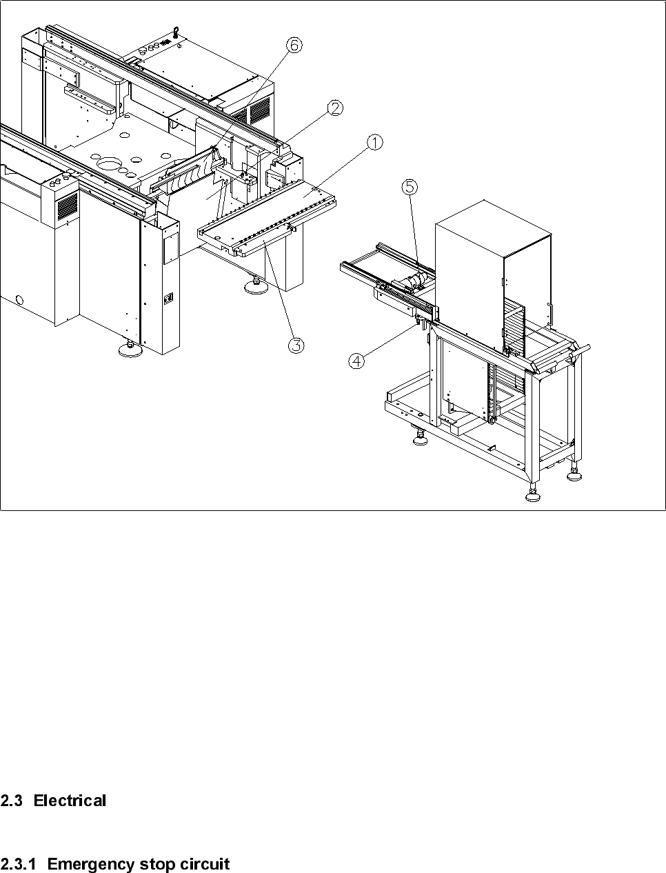
Figure 1
Key to figure 1:
① Components table
② Wafflepack changer guide plate
③ Docking rail
④ Centering pin
⑤ Spirit level
⑥ Used tape guide channel
Nachrüstanleitung/Retrofitting Instructions WPW an SIPLACE 80F3/F4 / WPC on SIPLACE 80F3/F4
Ausgabe 09/96 / 09/96 Edition
Seite/Page 9 von/of 12
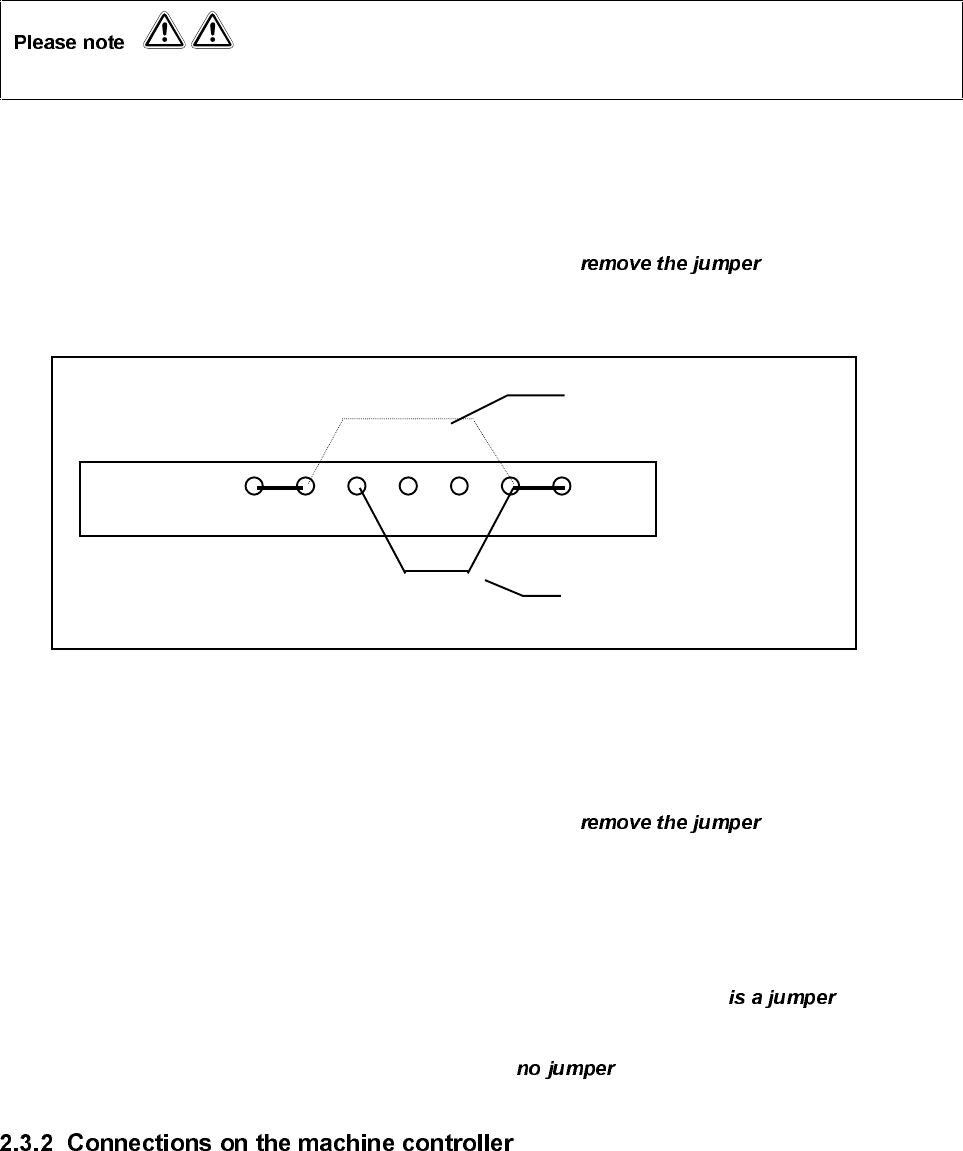
When wiring up the emergency stop circuit, check the delivery or product status of terminal panel Y904.
2.3.1.1 Delivery date before December 1994
•
On the left-hand terminal panel Y904 on terminal strip X211, from terminal 6 and
place the jumper on terminal 7 (see drawing).
Terminal panel Y904
X211
X5 X6 X7 X8 X9 X10 X10
2.3.1.2 Delivery date after January 1995
•
On the left-hand terminal panel Y904 on terminal strip X211, between terminal 5
and terminal 6.
2.3.1.3 Delivery date after January 1995 and product status of terminal panel Y904 PS 07.
•
On the left-hand terminal panel Y904 on terminal strip X211, check that there between
terminal 5 and terminal 6.
•
Then check terminal 6 and terminal 7. There must be between these terminals.
•
Plug cable F515-W1 on the wafflepack changer into plug X4sb on the machine controller.
•
Plug the cable on the short right-hand components table into plug X5sb on the machine controller.
•
Plug the cable on the left-hand components table into plug X6sb on the machine controller.
Wiring without WPC
Wiring with WPW