NR_WPW_WPC_F3_F4.pdf - 第21页
Nac hrüstanleitung/R etrofitting Instruc tions WPW an SIPLACE 80F3/F4 / WPC on SIP LACE 80F3/F4 Aus gabe 09/96 / 09/96 Edition Seite/ Page 9 von/ of 12 W hen w i ri ng up t he emer gency stop ci rc uit , c heck the del i…
WPW an SIPLACE 80 F3/F4 / WPC on SIPLACE 80 F3/F4 Nachrüstanleitung/Retrofitting Instructions
Ausgabe 09/96 / 09/96 Edition
Seite/Page 8 von/of 12
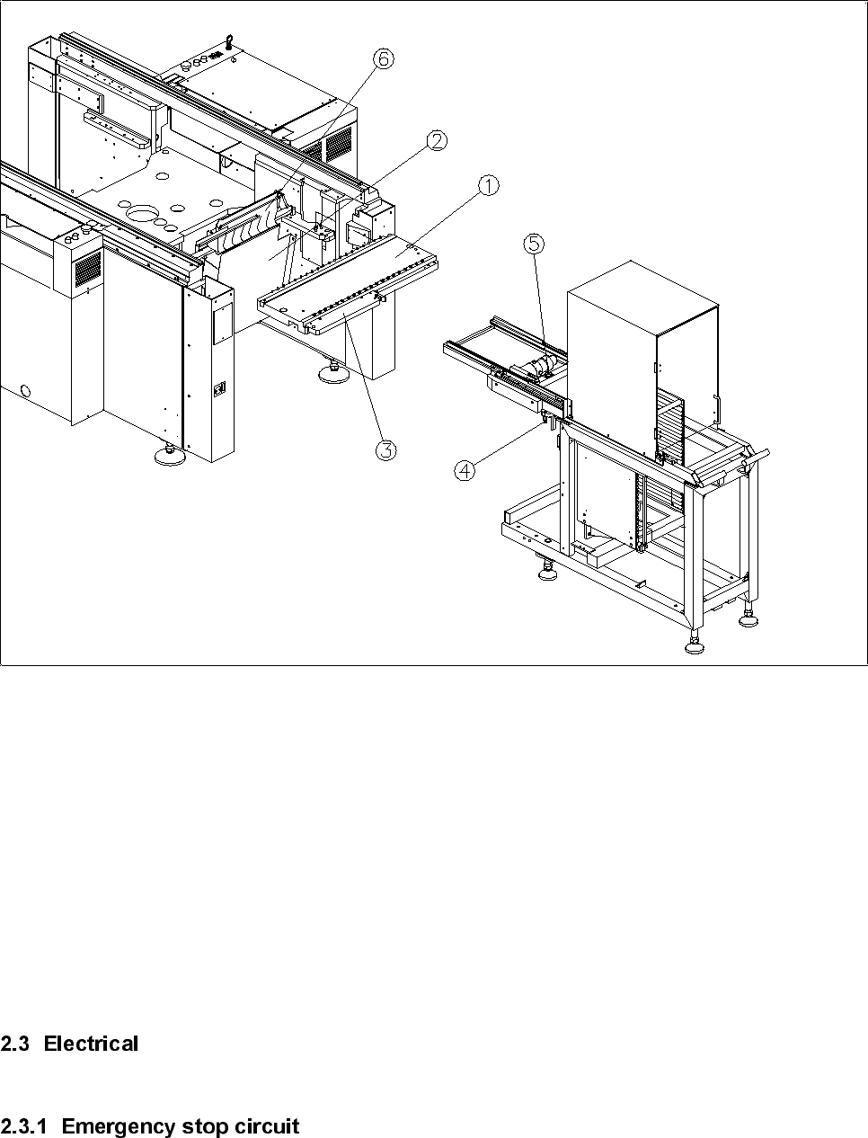
Figure 1
Key to figure 1:
① Components table
② Wafflepack changer guide plate
③ Docking rail
④ Centering pin
⑤ Spirit level
⑥ Used tape guide channel
Nachrüstanleitung/Retrofitting Instructions WPW an SIPLACE 80F3/F4 / WPC on SIPLACE 80F3/F4
Ausgabe 09/96 / 09/96 Edition
Seite/Page 9 von/of 12
When wiring up the emergency stop circuit, check the delivery or product status of terminal panel Y904.
2.3.1.1 Delivery date before December 1994
•
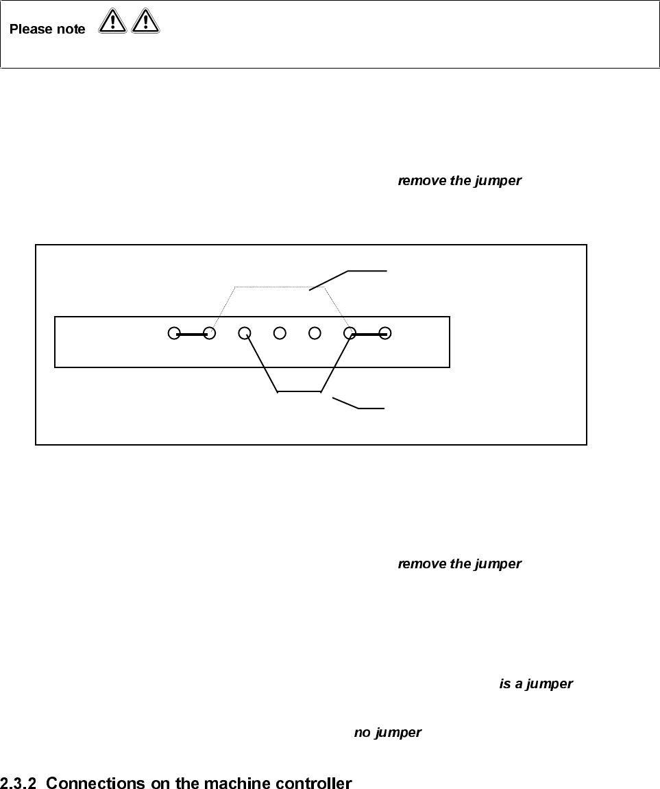
On the left-hand terminal panel Y904 on terminal strip X211, from terminal 6 and
place the jumper on terminal 7 (see drawing).
Terminal panel Y904
X211
X5 X6 X7 X8 X9 X10 X10
2.3.1.2 Delivery date after January 1995
•
On the left-hand terminal panel Y904 on terminal strip X211, between terminal 5
and terminal 6.
2.3.1.3 Delivery date after January 1995 and product status of terminal panel Y904 PS 07.
•
On the left-hand terminal panel Y904 on terminal strip X211, check that there between
terminal 5 and terminal 6.
•
Then check terminal 6 and terminal 7. There must be between these terminals.
•
Plug cable F515-W1 on the wafflepack changer into plug X4sb on the machine controller.
•
Plug the cable on the short right-hand components table into plug X5sb on the machine controller.
•
Plug the cable on the left-hand components table into plug X6sb on the machine controller.
Wiring without WPC
Wiring with WPW
WPW an SIPLACE 80 F3/F4 / WPC on SIPLACE 80 F3/F4 Nachrüstanleitung/Retrofitting Instructions
Ausgabe 09/96 / 09/96 Edition
Seite/Page 10 von/of 12
•
Boot up the Sitest using the Sitest start diskette.
•
Note the positions of the two heads and the gantry.
At present, table 2 cannot be measured using the PCB camera or Sitest. The table positions must be
measured manually using the calibration segment.
•
Using the segment removal tool, remove segment no. 7 (top segment) from the revolver head.
•
Insert the calibration segment.
•
Position the calibration segment in the bottom position.
•
Place the iron-type gauge on track 61 on table 2.
•
Disable the X and Y axes and push the gantry over the ‘iron’.
•
Disable the Z axis and manually position the main axes until the tip of the calibration segment is above
the indent of the ‘iron’.
Always check the position of the Z axis when moving the gantry.
•
Read the X and Y positions on the axis testing device and note the values.
•
Then place the ‘iron’ on track 120 on table 2 and repeat the measuring procedure.
•
When the measuring procedure is complete, switch the axes on again in the following :
⇒ ⇒
•
Insert the DOS diskette and edit .
•
Convert the measured track positions from digits into
µ
m (measured value x 2.5).
•
Enter the calculated values into Real.ma (see extract from Real.ma).