VI User Manual.pdf - 第85页
.TST file creation Vision 2007 4.10 User Manua l Rev 01 4 - 11 4.3.5 Computing tab The Way computing (d efault = 0) ( A ) is the number of camera passages to inspect the pane l (0 = the number of passage s is optimized b…
.TST file creation
4 - 10 Vision 2007 4.10 User Manual Rev 01
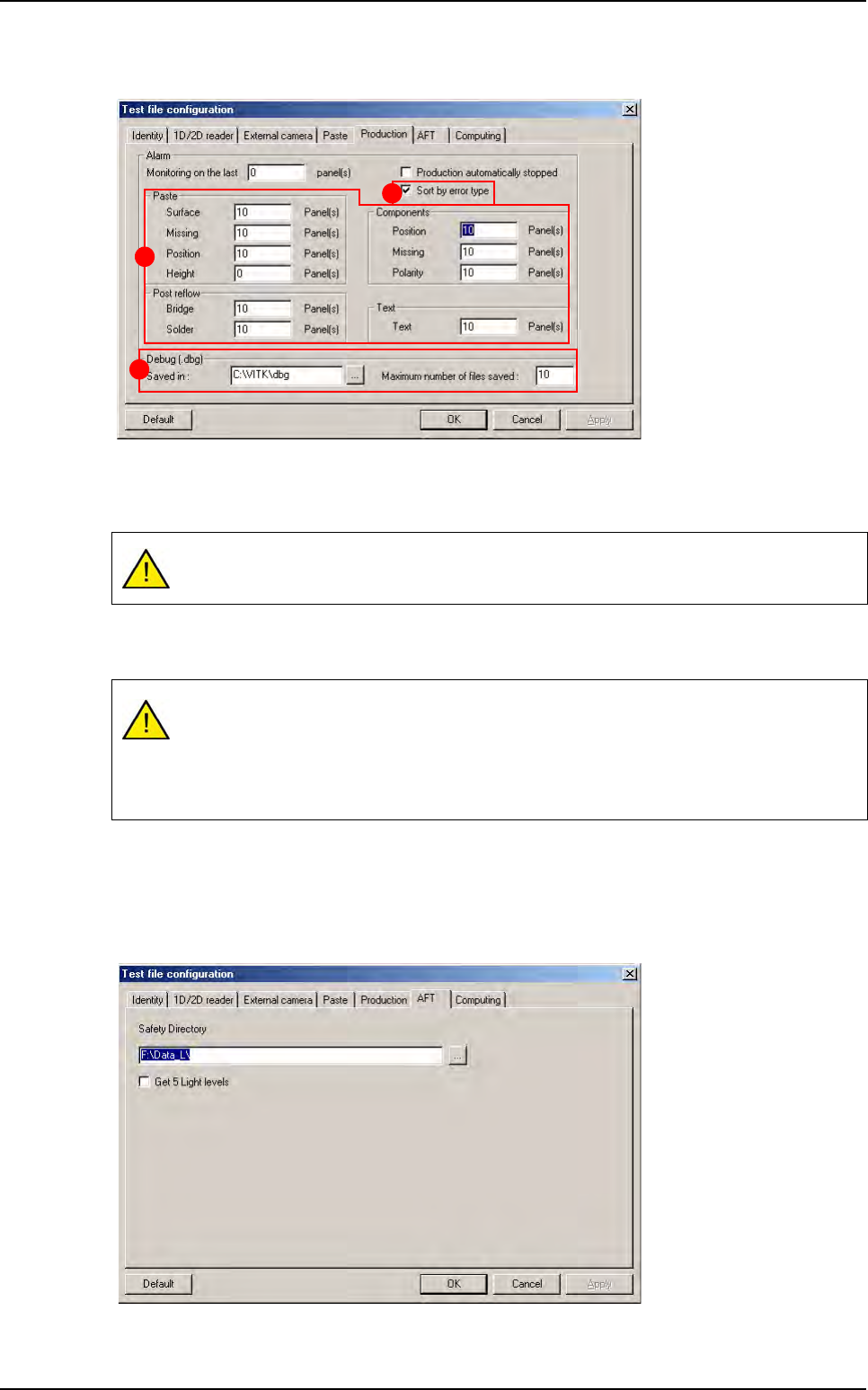
4.3.3 Production tab
The machine triggers an alarm after n boards (0 for no alarm).
The part (A) allows the operator to activate or no an alarm when there is more defects than the
autorized limit.
Tick
Sort by error type
(
B
) to sort errors by column on the table graph of the production screen.
If you deselect it, all the errors will be displayed in every columns
.
In the Debug (.dbg) section (C), enter the location to save DBG and the maximum number of
file saved.
4.3.4 AFT tab
File save address during AFT.
By default the limit of defect is fixed at 10. If it is 0, the limits are not active.
If you have 10 boards with position errors on the last 40 boards you will have an alarm
message in production. From this message box:
Select OK to stop production and reset the counter for all the limits.
Select Cancel to carry on and reset only the reached limit.
C
B
A
Configuring the .tst file
.TST file creation
Vision 2007 4.10 User Manual Rev 01 4 - 11
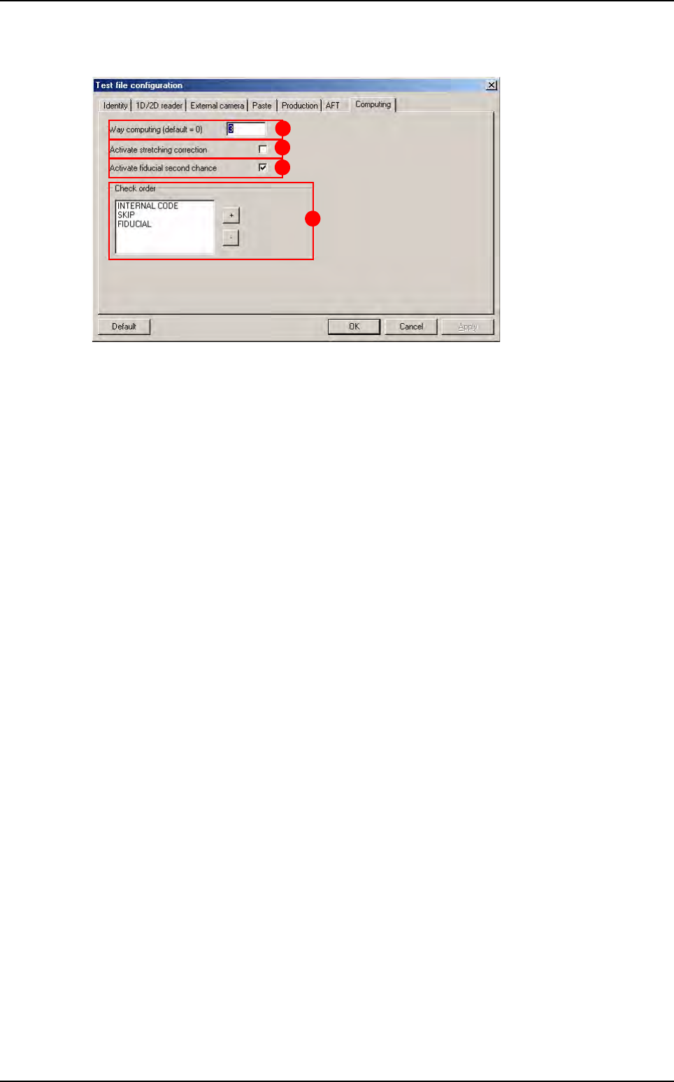
4.3.5 Computing tab
The
Way computing (default = 0)
(
A
) is the number of camera passages to inspect the panel
(0 = the number of passages is optimized by the software).
Activation of the stretching correction (
B
) (board expansion) with respect to the fiducials.
Activation of a second try (C), if fiducial fails in production: increase the search window 2 times.
In Check order (D) area, use + and - buttons to determine the inspection order of internal code,
skip and fiducial.
Click OK to confirm the configuration parameters.
D
A
B
C
Configuring the .tst file
.TST file creation
4 - 12 Vision 2007 4.10 User Manual Rev 01
4.4 Solder paste (optional)
To inspect solder paste on a board, you must import the gerber information on the .tst file.
4.4.1 Gerber file importation
Import the gerber file to the .tst file to obtain the graphic representation of the solder paste pads.
In the Test file menu go to Import sub menu and select Gerber File.
4.4.2 Create zones
Placing the zones in order to incorporate the solder paste pads and test them. In the Edit menu
go to Board sub menu and select Create zones.
A gerber file can only be imported to an existing .tst file.