QP-242E 工程师培训手册 (6.0).pdf.pdf - 第83页
FK-9F98-07 QP242E Training Text for Service Engineers 6th edition 8. MTU6 Adjustment [ 15 /16] Fuji Machine Mfg. Co., Ltd. Okazaki SMT Equipment Quality Assurance Dept. Technical Support Div. Section No.2 8- 15 [8 -2 3 ]…
FK-9F98-07 QP242E Training Text for Service Engineers
6th edition 8. MTU6 Adjustment [14/16]
Fuji Machine Mfg. Co., Ltd. Okazaki
SMT Equipment Quality Assurance Dept.
Technical Support Div. Section No.2
8-14
[8-21]
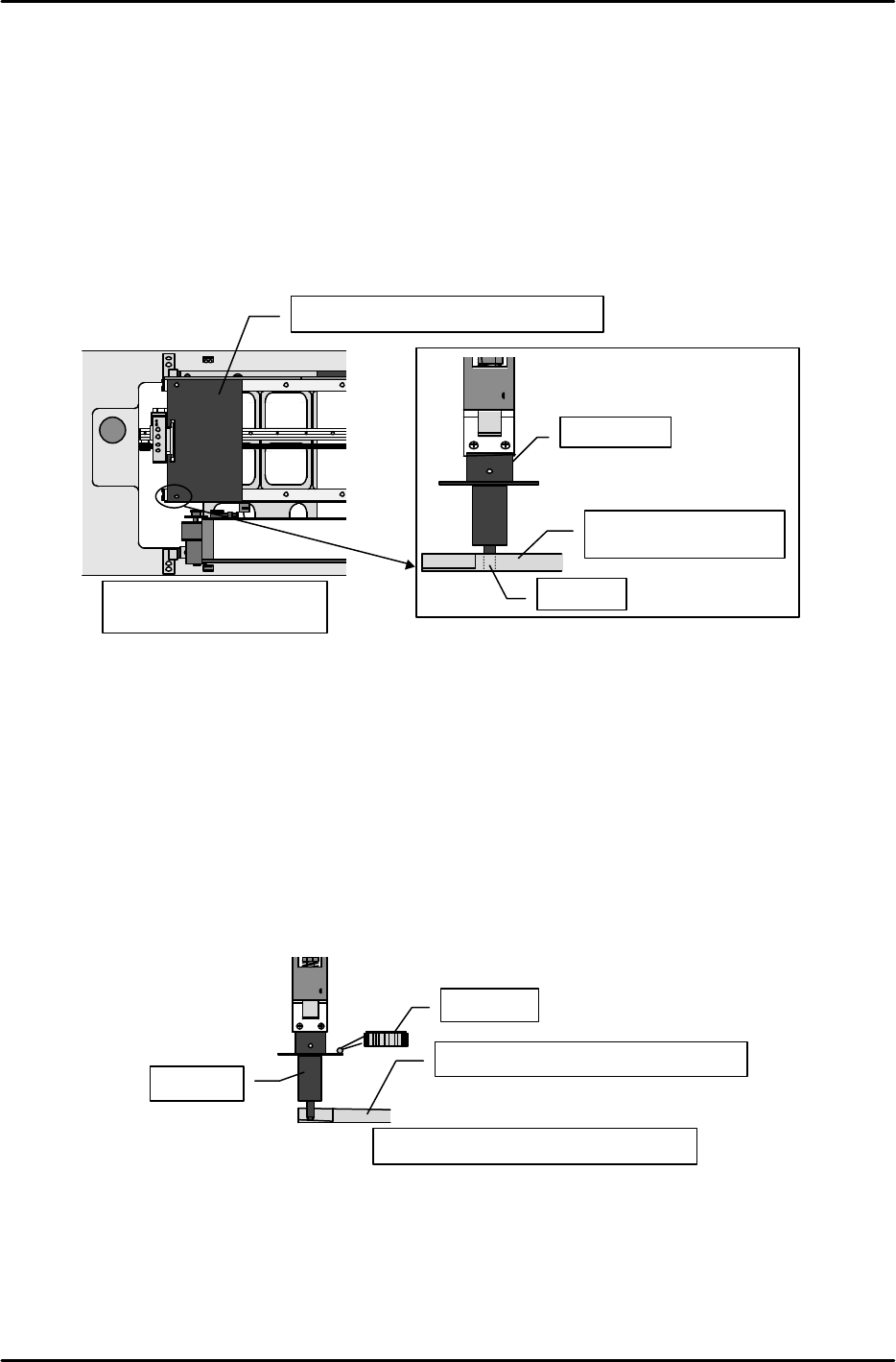
Device_Origin_MTU6D0_X,Y
1) Set the nozzle jig.
2) Move the shuttle to the advance limit using the following command operation: [POSITION],
[MTU], [SHUTTLE], [ADVANCE], and press START. At this position measure the Proper
data for the left rear corner that is used as a reference when a tray is set in the tray holder.
3) Set the tray Proper data measurement jig on the shuttle at the advance limit.
4) Move the head to a position where the end of the nozzle jig will fit in the 3.0 mm hole in the
left rear of the jig.
5) In this position use the following command operation to automatically enter the Proper data;
[PROPER], [ETC], [DEVICE], [ORG. POS], [X1, Y1], and [SET].
6) Likewise, measure X2, Y2 at the right rear hole position and automatically enter the Proper
data.
[8-22] Pickup_Height_MTU6D_Z
1) Set the nozzle jig.
2) Verify that the tray Proper data measurement jig is at the advance limit.
3) Lower the Z-axis and at the position where the top of the notch on the left rear of the tray
Proper data measurement jig makes contact with the bottom of the jig, set the dial gauge on
the top of the luminescent disk.
4) Slowly raise the Z-axis to find the location at which the dial gauge beg ins to move.
5) This Z-axis position is Z01. Use the following command operation to automatically enter
the Proper data; [PROPER], [ETC], [DEVICE], [ORG. POS.], [Z1], and [SET].
6) Use the same procedure to measure Z2 at the right rear notch and then automatically enter
the Proper data.
Measure at the shuttle
advance limit position
Tray Proper data measurement jig
Nozzle jig
Tray Proper data
measurement jig
3mm hole
Tray Proper data measurement jig
Measure at the advance limit position
Nozzle jig
Dial gauge
FK-9F98-07 QP242E Training Text for Service Engineers
6th edition 8. MTU6 Adjustment [15/16]
Fuji Machine Mfg. Co., Ltd. Okazaki
SMT Equipment Quality Assurance Dept.
Technical Support Div. Section No.2
8-15
[8-23]
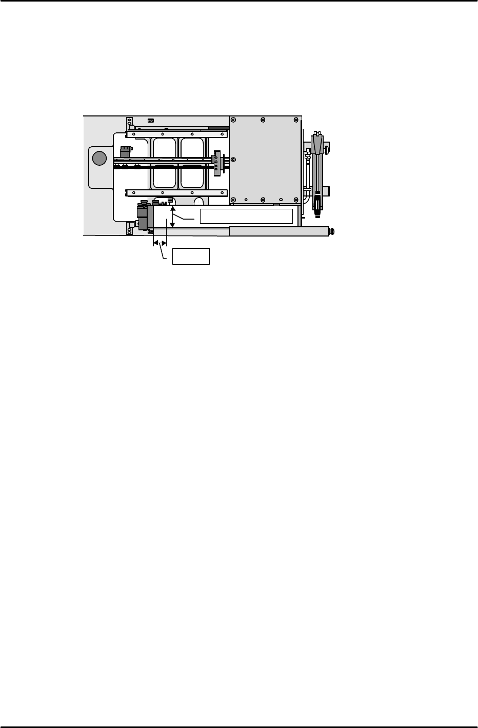
MTU_Parts_Eject_Pos.CV_X,Y
1) Set the nozzle jig.
2) Enable the servo lock status in the position where the center of the tip of the nozzle jig is 50
mm from the center of the reject parts conveyor in the X-direction and 50 mm from the back
side of the conveyor in the Y-direction.
3) This position is the MTU_Parts_Eject_Pos.CV_X & Y position. Use the following command
operation to automatically enter the Proper data; [PROPER], [ETC], [REJECT POS],
[CONVEYOR], and [SET].
[8-24] Proper Data Transmission to F4G
Once measurement of all Proper data items has been completed, transmit theProper data
back to F4G.
★
50mm
Center of the conveyor

FK-9F98-07 QP242E Training Text for Service Engineers
6th edition 8. MTU6 Adjustment [16/16]
Fuji Machine Mfg. Co., Ltd. Okazaki
SMT Equipment Quality Assurance Dept.
Technical Support Div. Section No.2
8-16
*****This page does not contain any contents.