QP-242E 工程师培训手册 (6.0).pdf.pdf - 第91页
FK-9F98-07 QP242E Training Text for Service Engineers 6th edition 10. STU Adjustment & Operation Check [ 5 /8] Fuji Machine Mfg. Co., Ltd. Okazaki SMT Equipment Quality Assurance Dept. Technical Support Div. Section …
FK-9F98-07 QP242E Training Text for Service Engineers
6th edition 10. STU Adjustment & Operation Check [4/8]
Fuji Machine Mfg. Co., Ltd. Okazaki
SMT Equipment Quality Assurance Dept.
Technical Support Div. Section No.2
10-4
[10-7]
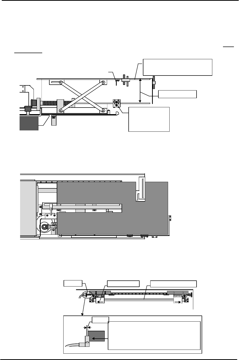
Tray Holder Lower Limit Sensor Adjustment
The tray holder position at which adjustment in the previous section finished should be the lower
limit. Mark the position of the top of the tray holder. Then go to the I/O and just as was done in the
previous section raise the holder with no board loaded. Verify that the distance from the marked
position to the top of the tray holder when it stops at the tray position check sensor is greater than
the maximum tray stacking height of 50 mm.
If the distance is less than 50 mm then lower the mounting bracket to adjust the distance to more
than 50 mm.
[10-8]
Tray Holder Parallel Measurement
Use a dial gauge to measure the parallelism of the top of the tray holder at the upper limit and lower
limit.
[10-9]
Tray Remover Forward and Retract Limit Adjustment
When at both the forward limit and retract limit mechanical stopper positions, loosen the dog and
move it until the sensor goes off. Then move the dog back to find the position at which the sensor
comes on. From this position move the dog back another 1 mm and secure it in place.
Forward limit
Retract limit
Mecha-stopper Remover air cylinderDog
1mm
Move the dog while at the mechanical
stopper position. Move the dog another
1 mm from the position at which the
sensor comes on and secure the dog in
place in that position.
Raise or lower
the sensor to
adjust the
distance to more
More than
50mm
Dog
Tray holder
Upper limit when stopped at
the tray position check sensor.
( )
View from
the top of
the STU
①
②③
④
⑤
⑥⑦
Tolerance : within 0.5mm
1.( )
2.( )
3.( )
4.( )
5.( 0mm)
6.( )
7.( )
FK-9F98-07 QP242E Training Text for Service Engineers
6th edition 10. STU Adjustment & Operation Check [5/8]
Fuji Machine Mfg. Co., Ltd. Okazaki
SMT Equipment Quality Assurance Dept.
Technical Support Div. Section No.2
10-5
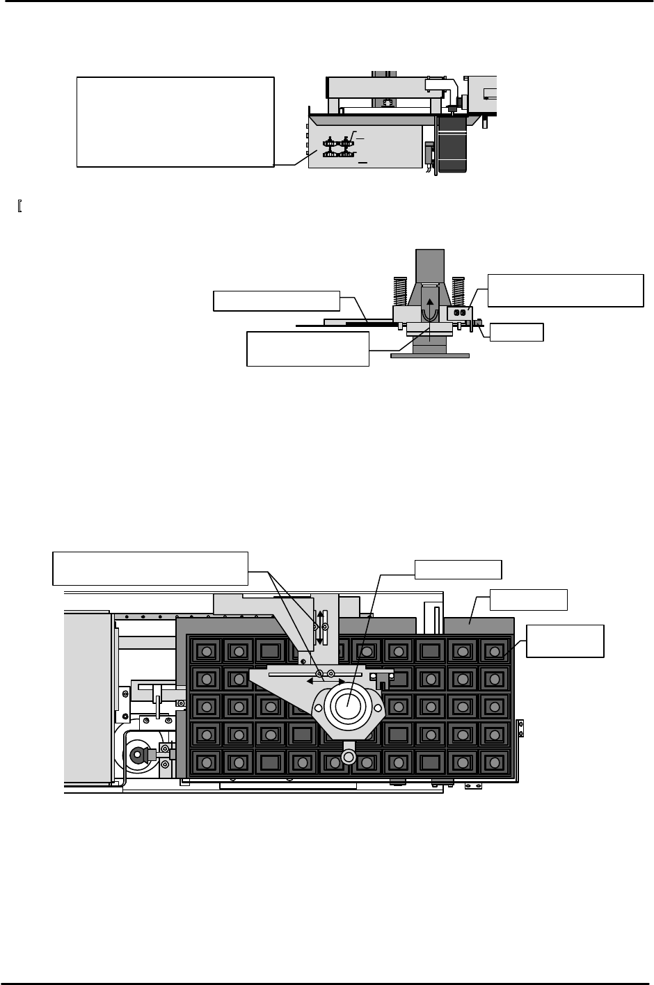
[10-10]
Tray Remover Forward and Retract Speed Adjustment
Adjust the forward and retract speed as follows using the speed controllers installed on the side of
the STU control box.
[
10-11]
Tray Remover Upper Limit Sensor Adjustment
1) Insert a 2 mm clearance gauge so that the remover is elevated.
2) Move the dog to adjust the upper limit sensor so that it comes on in this 2 mm elevated position.
[10-12] Tray Remover Provisional Position Adjustment
1) Set a standard 100-pin size empty tray in the STU tray holder.
2) Advance the remover.
3) Move the remover mount bracket to adjust it so that the center of the remover aligns with the
center of the empty tray.
* Since the STU itself is not servo controlled, the tray remover position must be moved to the center
of the tray dimensions of each tray type. The standard 100-pin size tray is used here for measuring
but other boards should be adjusted to match each tray size.
Use the dog to adjust the
sensor so that it comes on.
Sensor
2mm feeler gauge
Raise 2 mm using
the
feeler
gauge
View from the
side of the STU
Tray eject box
Advance
Retract
From the fully closed status
Top right Open 5.25 turns
Top left Open 1.5 turns
Bottom right Open 2.5 turns
Bottom left Open 6.25 turns
Move the bracket and then
move the remover to the center.
View from
top of STU
Tray holder
Empty tray
(100pin)
Tray
FK-9F98-07 QP242E Training Text for Service Engineers
6th edition 10. STU Adjustment & Operation Check [6/8]
Fuji Machine Mfg. Co., Ltd. Okazaki
SMT Equipment Quality Assurance Dept.
Technical Support Div. Section No.2
10-6
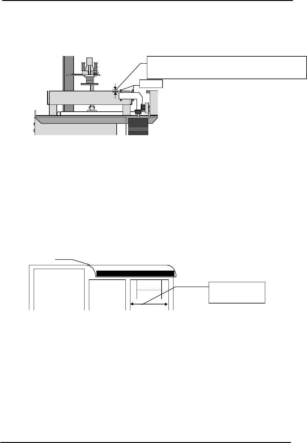
[10-13] Tray Eject Sensor Adjustment
1) Loosen the hollow bolt and adjust so that the distance from the top of the sensor mount bracket to
the top of the sensor is 5 mm and so the sensor amp is on.
2) When the transparent tray eject box is set after the sensor has been adjusted, verify that the
sensor light beam is positioned 1 mm above the box.
[10-14] STU Operation Check
1) Transmit a program for placing one tray of QF 100 pin parts to the machine.
2) Check the part name and set the part on the STU.
3) Attach the nozzle to be used on the nozzle holder or on the nozzle change unit.
4) Activate automatic operation and confirm that the STU works properly.
[10-15] Remover Operation Check
Load a 240 g empty tray (maximum allowable weight) on the STU and verify that the remover is
able to hold the tray.
[10-16] Check of Restrictions When STU is Installed
When an STU-1 or STU-2 is set on the MFU there are restrictions that apply to the feeder
positions as outlined below. Verify that the setup is in conformance with these restrictions.
View from the side of the STU
Tray eject box
Sensor
Move up or down to adjust both sensors to 5 mm together.
After adjusting verify that the distance between the top of
the tray eject box and the sensor light beam is 1 mm.
MFU
Reject
parts
conveyor L
or M type
STU 1 or 2
Device positions
at which feeders
can be set