西门子SIPLACE HS 60-设备参数_EN.pdf - 第30页
28 Machine Criteria: Mapping (Option) Technical Data Dimensions of the mapping test plate 508 x 450 mm 2 (for single conveyor) 508 x 380 mm 2 (for flexible dual conveyor) Number of measurement points 13 x 11 (standard re…
27
Machine Criteria:
Placement Reliability
Description
In addition to correct positioning,
placement reliability is important.
On the SIPLACE HS-60 this is en-
sured through a number of control
functions, such as vacuum checks
and component vision testing dur-
ing the placement sequence.
Out of tolerance components are
rejected, placed on the repair list
and automatically processed dur-
ing a repair cycle. An offset in the
position of the PCB relative to the
conveyor system (PCB vision) and
an offset of the X-axis, Y-axis or ro-
tation of the component relative to
the midpoint of the nozzle (com-
ponent vision) trigger an immedi-
ate correction to ensure place-
ment accuracy.
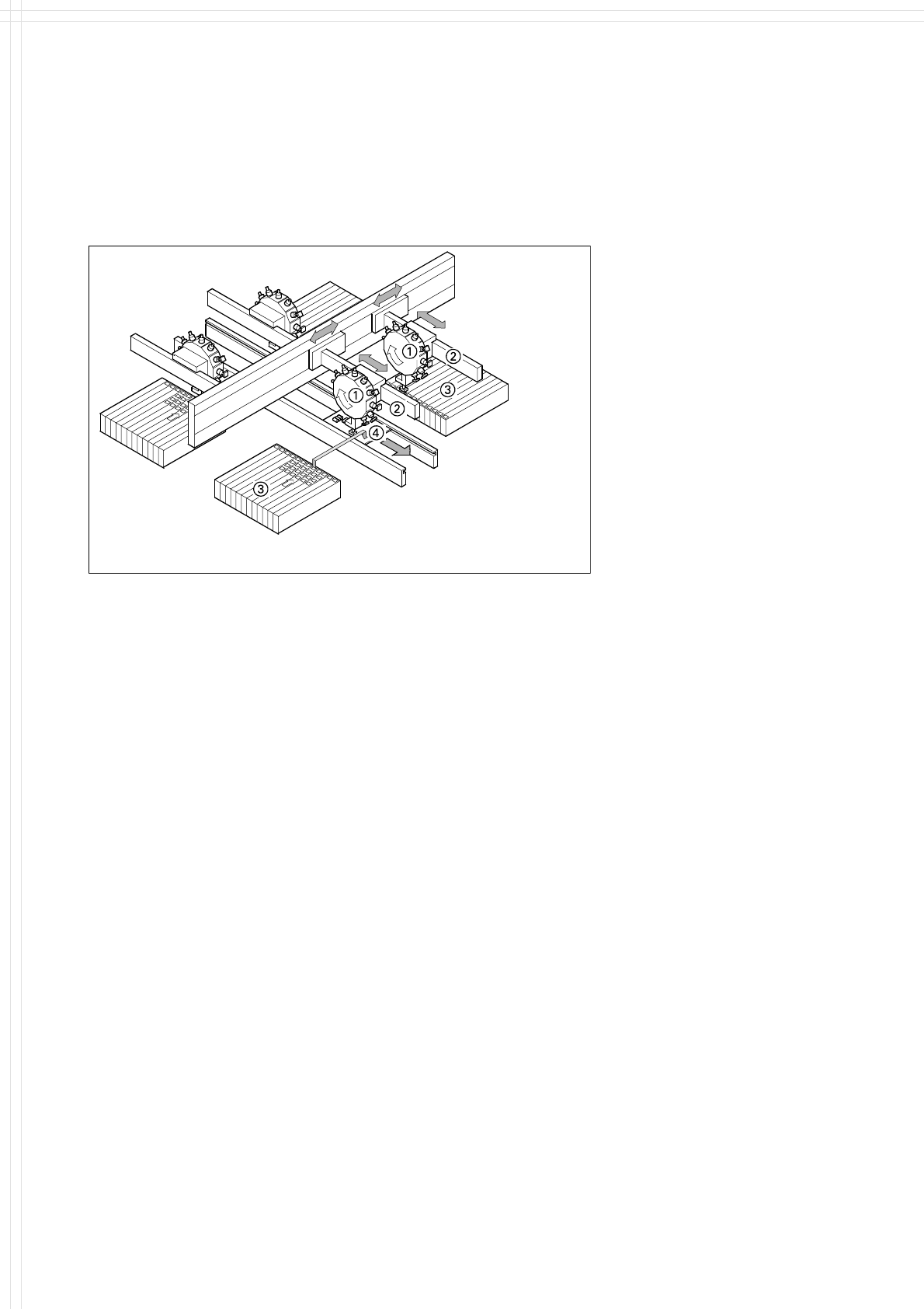
ℵ 12-Nozzle Collect & Place Head
ℑ X-/Y-Gantry System
ℜ Fixed Component Supply
℘
Fixed PCB
Placement Principle SIPLACE HS-60
Since the PCB is fixed, the com-
ponents remain in the exact posi-
tion they are placed. The station-
ary component table ensures a
precise pick up. Options, such as
the component bar code scanner,
can be added to further enhance
reliability.
28
Machine Criteria:
Mapping (Option)
Technical Data
Dimensions of the mapping
test plate
508 x 450 mm
2
(for single conveyor)
508 x 380 mm
2
(for flexible dual conveyor)
Number of measurement
points
13 x 11 (standard resolution)
26 x 21 (high resolution)
Ambient temperature
during calibration
+ 20° ± 3°C
Components of the option Test plate (special glass)
Calculation data (disk)
Case for secure storage
Description
Slight distortions of the gantry
axes cannot always be avoided
despite the highly stable machine
frame. With the aid of the map-
ping approach, the high placement
precision of the machine is main-
tained throughout its service life.
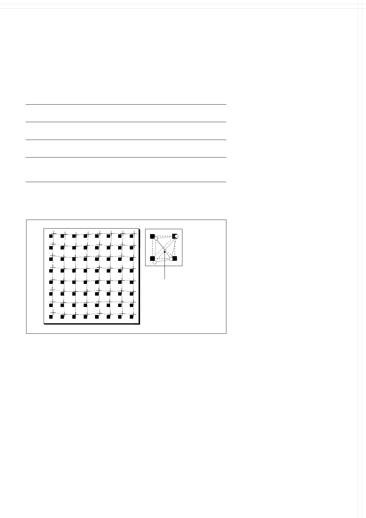
With this calibrating procedure,
which can be conducted quickly
and easily, the PCB camera recog-
nizes the fiducials on a mapping
calibration plate placed in its oper-
ating area. This board has highly
accurate marks on it. Any distor-
tions are located by comparing the
nominal grid on the mapping board
with the actual grid ”drawn” by
the placement head. These distor-
tions are then considered when
calculating all further positioning of
the X-/Y-axis and are thus com-
pensated for.
Nominal Grid of Mapping Plate and Actual Grid with
Deviations Due to Gantry
Corrected
Position

29
SIPLACE Software Architecture:
Line Programming System
Station Computer
Functions
Line Programming System for
Software
Data Preparation
Optimization
Line control
Line monitoring
Data management
LRL 503.xx (Linux) or
SIPLACE Pro 2.x (Windows XP)
Station Computer for
Software
Machine control
Machine monitoring
Machine operation
SW 503.xx
SW 505.xx
Description
Line Programming System
The Line Programming Systems
program, optimize and control
complete SIPLACE placement
lines. Consequently secondary
times are reduced and maximum
productivity is guaranteed.
To meet these targets, two
software programs can be used:
The Linux based LRL (Linux Line
Computer), or SIPLACE Pro,
which runs on standard PC
with Windows XP.
Station Computer
The station computer in conjunc-
tion with the machine controller
with its realtime capability per-
forms the following jobs: digital
control of the machine gantry
systems; control of PCB input
and output and of PCB transport;
monitoring functions, handling of
malfunctions and output of error
messages (including Help system);
ensuring the optimal quality of the
placement process.
For more details and information on
further software options please see
SIPLACE Software Specification.
Line Programming System
Station Computer