西门子SIPLACE HS 60-设备参数_EN.pdf - 第32页
30 Technical Data: Signal Interfaces Signal Interface (20-Pin Ribbon Cable Connector) to upstream station x3 to downstream station x4 Pin 13 GND 24 V Pin 10 Reserved Pin 14 Arrived Pin 9 Reserved Pin 15 Permission Pin 8 …
29
SIPLACE Software Architecture:
Line Programming System
Station Computer
Functions
Line Programming System for
Software
Data Preparation
Optimization
Line control
Line monitoring
Data management
LRL 503.xx (Linux) or
SIPLACE Pro 2.x (Windows XP)
Station Computer for
Software
Machine control
Machine monitoring
Machine operation
SW 503.xx
SW 505.xx
Description
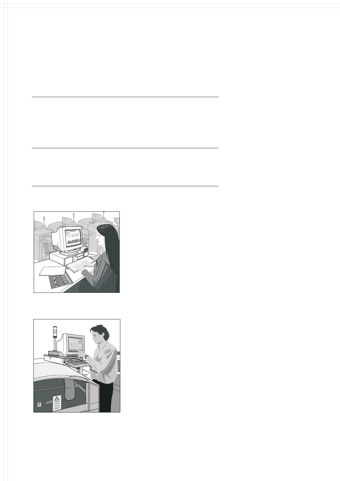
Line Programming System
The Line Programming Systems
program, optimize and control
complete SIPLACE placement
lines. Consequently secondary
times are reduced and maximum
productivity is guaranteed.
To meet these targets, two
software programs can be used:
The Linux based LRL (Linux Line
Computer), or SIPLACE Pro,
which runs on standard PC
with Windows XP.
Station Computer
The station computer in conjunc-
tion with the machine controller
with its realtime capability per-
forms the following jobs: digital
control of the machine gantry
systems; control of PCB input
and output and of PCB transport;
monitoring functions, handling of
malfunctions and output of error
messages (including Help system);
ensuring the optimal quality of the
placement process.
For more details and information on
further software options please see
SIPLACE Software Specification.
Line Programming System
Station Computer
30
Technical Data:
Signal Interfaces
Signal Interface (20-Pin Ribbon Cable Connector)
to upstream station x3 to downstream station x4
Pin 13 GND 24 V Pin 10 Reserved
Pin 14 Arrived Pin 9 Reserved
Pin 15 Permission Pin 8 Reserved
Pin 19 Request Pin 4 +30 V DC
unsaturated
Pin 20 GND 24 V for request / re-
leased (contact separation)
Pin 5 GND 24 V
Pin 18 Released Pin 6 +24 V DC
Pin 12 Trouble signal loop Pin 11 Trouble signal loop
Pin 11 Pin 12
Pin 3 +24 V DC Pin 15 Permission
Pin 2 GND 24 V Pin 13 GND 24 V for per-
mission / arrived
(contact separation)
Pin 1 +30 V DC unsaturated Pin 14 Arrived
Pin 8 Reserved Pin 18 Released
Pin 9 Reserved Pin 19 Released
Pin 10 Reserved Pin 20 GND 24 V
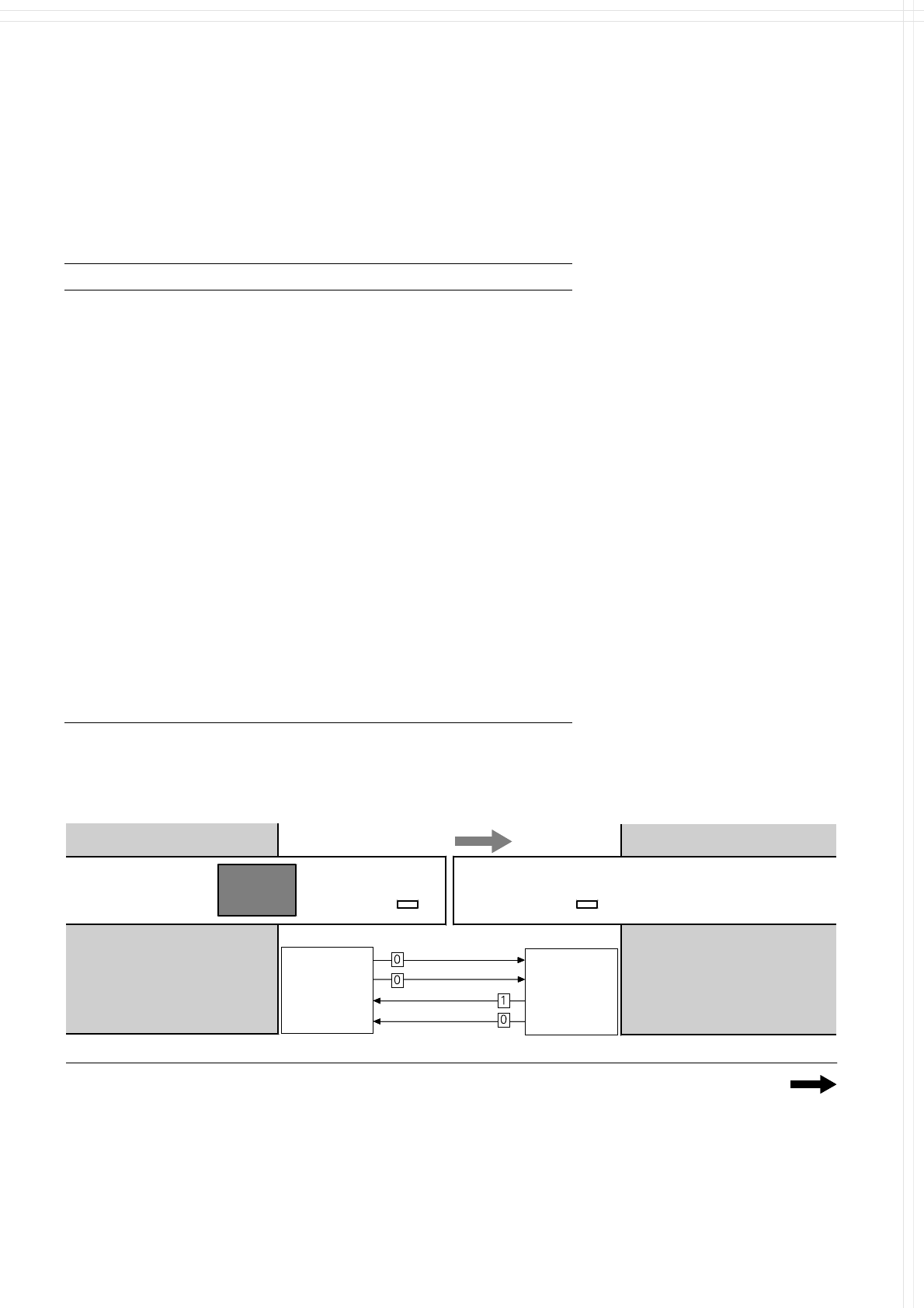
1. After switching-on the station
Transport Direction
PCB
Sensor
PCB
Sensor
Conveyor Section 1
Conveyor Section 2
Conveyor 1 is On Conveyor 2 is Off
Station n
transports
PCB
to delivery
Station n+1
is ready to
receive PCBs
Requirement
Delivery
Permission
Receival
Requirement
Delivery
Permission
Receival
31
Technical Data:
Signal Interfaces
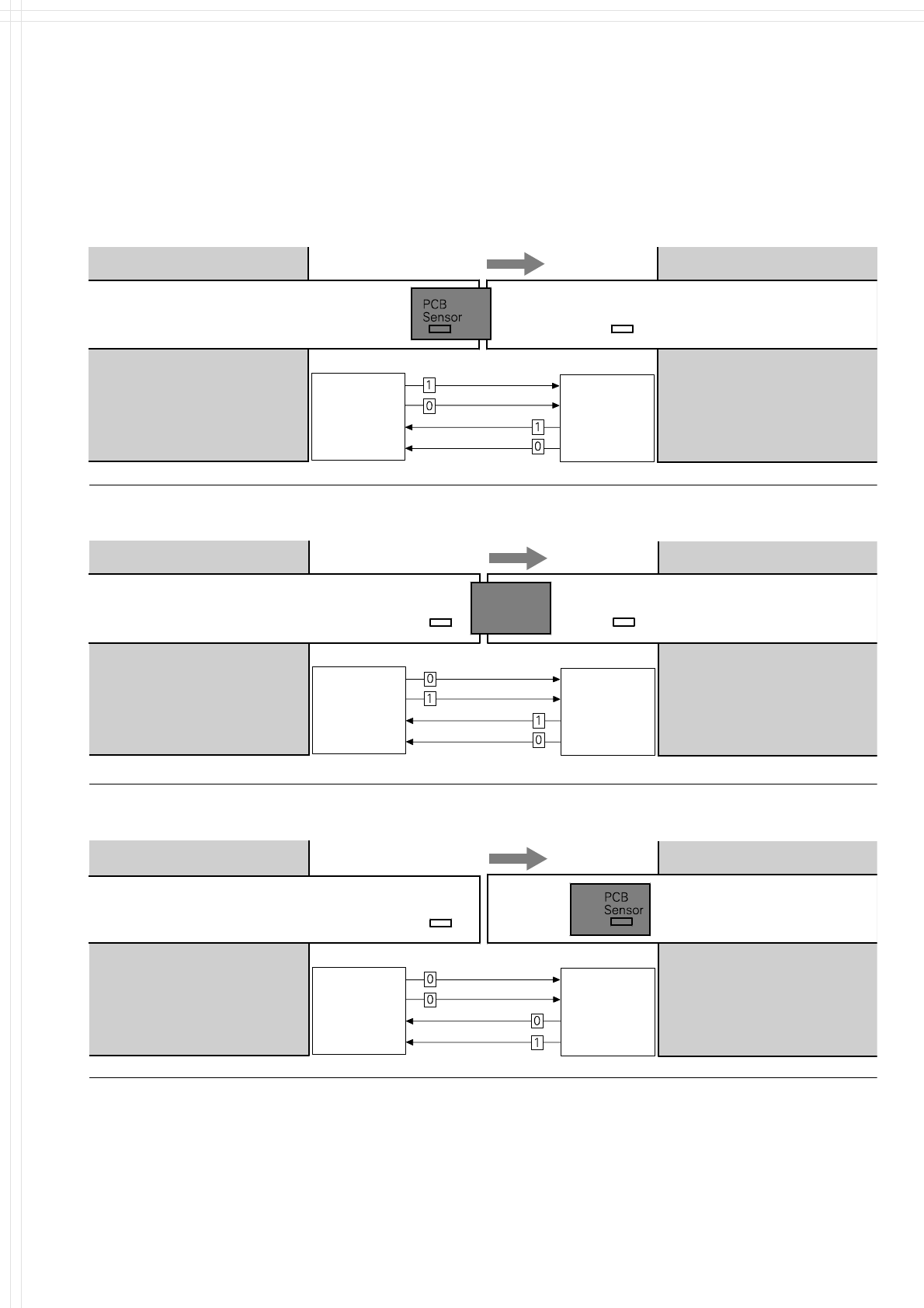
2. PCB handling has started
Transport Direction
Conveyor 1 is On Conveyor 2 is On
Conveyor Section 1
Conveyor Section 2
Station n
delivers PCB
to station n+1
Station n+1
waits for PCB
from station n
PCB
Sensor
Requirement
Delivery
Requirement
Delivery
Permission
Receival
Permission
Receival
Transport Direction
Conveyor Section 1
PCB
Sensor
Conveyor Section 2
PCB
Sensor
Station n
has just
delivered PCB
Station n+1
waits for PCB from
station n, but has
not received it
Requirement
Delivery
Permission
Receival
Requirement
Delivery
Permission
Receival
3. PCB is at delivery
Conveyor 1 is Off Conveyor 2 is On
Conveyor 1 is Off Conveyor 2 is On
Transport Direction
Conveyor Section 1
PCB
Sensor
4. PCB transport is finished
Conveyor Section 2
Station n
Station n+1
has just received
the PCB
Requirement
Delivery
Permission
Receival
Requirement
Delivery
Permission
Receival
A detailed documentation of the
PCB transport signal interface is
available on request.