西门子SIPLACE HS 60-设备参数_EN.pdf - 第9页
7 Placement Heads: Placement Accuracy Component Range Placement Accuracy a Placement Head Placement Accuracy 12-Nozzle Collect & Place Head 12-Nozzle Collect & Place Head with DCA (Option) X/Y Accuracy ± 60.0 µm …
6
Placement Heads
Description
The 12-Nozzle placement head
operates on the Collect & Place
principle.
An improved software leads to
quicker acceleration respectively
stopping of the placement head,
thus increasing the placemant rate
of SIPLACE HS-60 to 60,000 cph.
Each of its four X/Y-gantries
features one high-speed 12-Nozzle
Collect & Place Head.
At two gantries components are
picked up while at the other two
gantries components are placed.
Each head features an intelligent
Z-axis, Theta-axis for rotation and
vacuum monitoring.
Z-axis is learning both pick-up and
placement Z-height and thus opti-
mizes speed without compromis-
ing the programmed placement
forces.
Vacuum monitoring ensures low
component reject rates and high
quality placement.
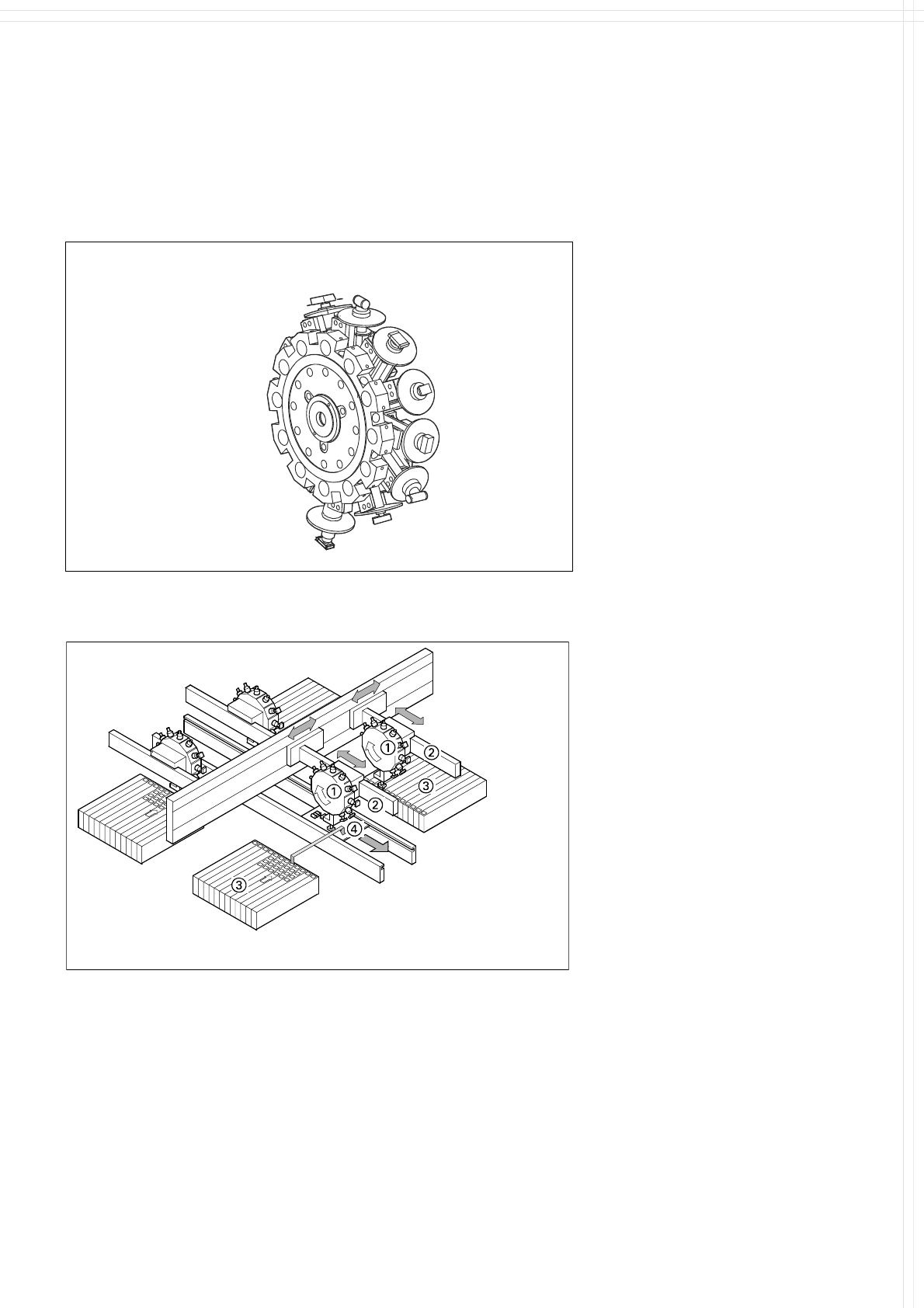
Placement Principle of SIPLACE HS-60
ℵ 12-Nozzle Collect & Place Head
ℑ X-/Y-Gantry System
ℜ Fixed Component Supply
℘
Fixed PCB
12-Nozzle
Collect & Place
Head
12-Nozzle Collect & Place Head for Very High Speed Placement

7
Placement Heads:
Placement Accuracy
Component Range
Placement Accuracy
a
Placement Head
Placement Accuracy
12-Nozzle
Collect & Place Head
12-Nozzle
Collect & Place Head
with DCA (Option)
X/Y Accuracy ± 60.0 µm ± 56.25 µm
3 Sig-
ma
Rot.-Accuracy ± 0.525° ± 0.525°
X/Y Accuracy ± 80.0 µm ± 80.0 / 75.0 µm
a
4 Sig-
ma
Rot.-Accuracy ± 0.700° ± 0.700°
X/Y Accuracy ± 120.0 µm ± 112.5 µm
6 Sig-
ma
Rot.-Accuracy ± 1.050° ± 1.050°
a) As defined in Scope of Service and Delivery SIPLACE.
Component Range
12-Nozzle
Collect & Place Head
12-Nozzle
Collect & Place Head
with DCA (Option)
Component size
0.6 x 0.3 mm
2
to
18.7 x 18.7 mm
2
0.6 x 0.3 mm
2
to
13 x 13 mm
2
Max. component height 6 mm 6 mm
Max. component weight 2 gr 2 gr
Placement force 2.4 - 5.0 N 2.4 - 5.0 N
Performance See table on page 3 See table on page 3
Min. pitch lead / bump
b
500 / 350 µm 400 / 200 µm
Min. ball / bump diam.
b
200 µm 110 µm
b) Depends also on specification of components (quality, vision...)
8
Placement Heads:
12-Nozzle Collect & Place Head
for Very High Speed Component Placement
Technical Data
Stroke of Z-axis max. 16 mm
Programmable placement force 2.4 to 5.0 N
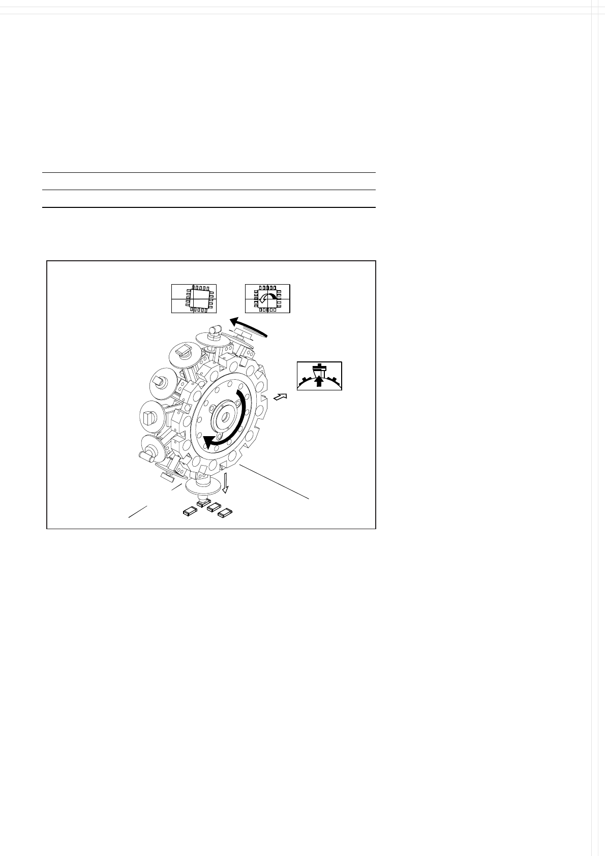
12-Nozzle Collect & Place Head for Very High Speed Placement
Component Pick-Up/
Placement
Segment
Removal
Point
Turning to
the Placement
Position
Component
Vision
Description
The 12-Nozzle placement head
operates on the Collect & Place
principle. The 12 vacuum nozzles
of the SIPLACE Collect & Place
Head rotate around a horizontal
axis. In addition to space savings
this offers the following benefits:
Due to the small diameter the
centrifugal forces are significantly
lower. The results are high-speed,
reliable placement and the same
cycle time for all components.
Components are picked up and
placed reliably with the aid of vac-
uum followed by a gentle air kiss.
A number of vacuum tests moni-
tors if the component has been
picked up and placed accurately.
Various control and self-learning
functions further enhance the de-
pendability of the system:
The optical recognition of feeder
positions records the exact po-
sition of the feeder table.
A camera on the placement head
(component vision module) de-
termines the exact position of
each component on the nozzle.
For every feeder the pick-up
offsets are averaged over the
last ten pick-ups. This enables
the head to dial-in on the pre-
cise pick point for each compo-
nent.
In addition, the package form is
also checked. If the actual geo-
metric dimensions of the com-
ponent do not correspond to
those programmed, the compo-
nent is rejected.
Components rejected by the vi-
sion system are dumped into a
bin, reject feeder or matrix tray.
Any rejected component gets
automatically placed during a
repair run.
Warpage of the PCB is accom-
modated by sensor stop acti-
vated z-axis placement. The sys-
tem also keeps the last ten
positions of the z-axis at com-
ponent placement and uses the
average of these values to im-
prove the drive down and place
speed of the cycle.
To check very small compo-
nents, such as 0201, it is helpful
to use a component sensor.
This infra-red sensor checks the
presence of components before
pick-up and placement, ensuring
reliable handling of even the
smallest components.