IPC-CM-770D-1996.pdf - 第167页
January 1996 IPC-CM-770 30.6.5.5 Combination Methods These solder extraction methods provide controlled combinations of heat, pressure, vacuum, and airflow for the controlled removal of any sol- der joint configuration. …
IPC-CM-770
Januaty
1996
IPC-I-
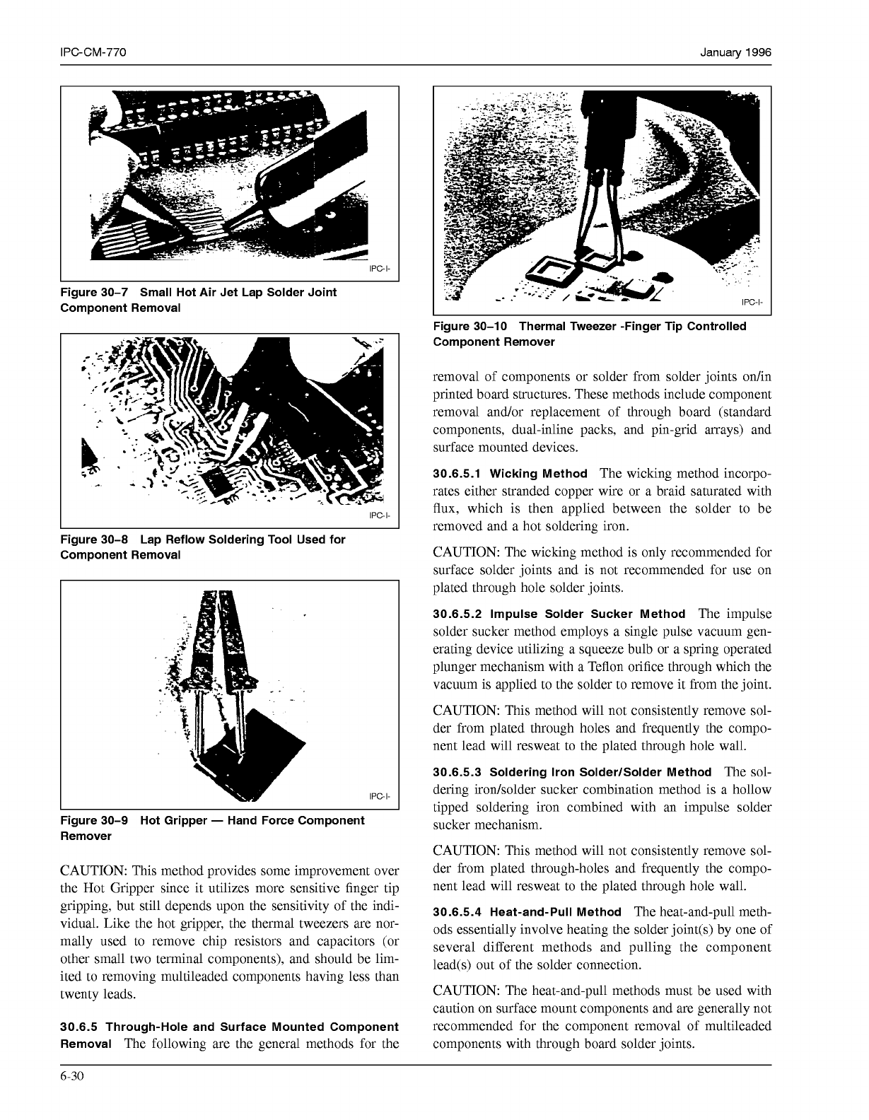
Figure 30-7 Small Hot Air Jet Lap Solder Joint
Component Removal
IPC-I-
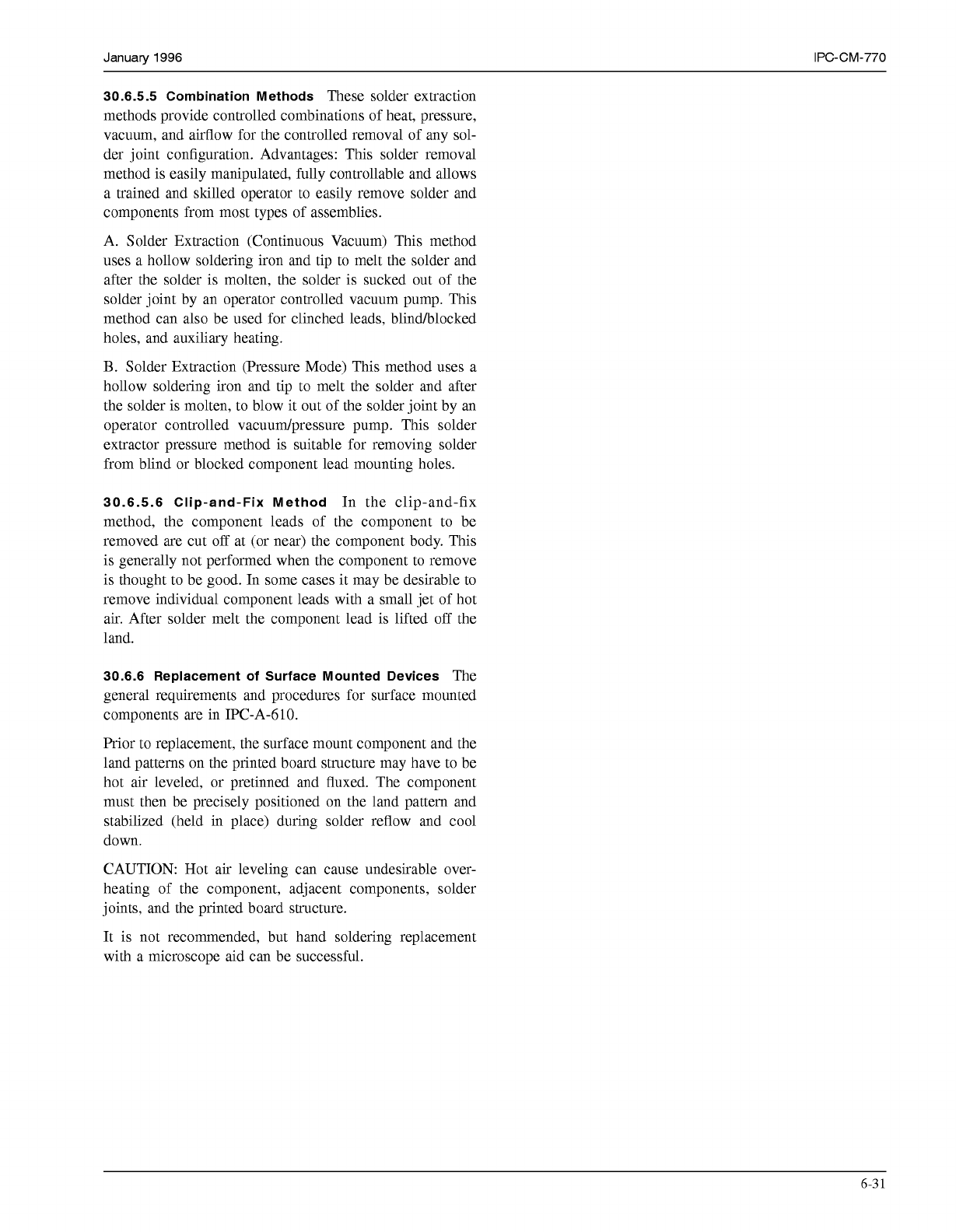
Figure 30-8 Lap Reflow Soldering Tool Used for
Component Removal
IPC-I-
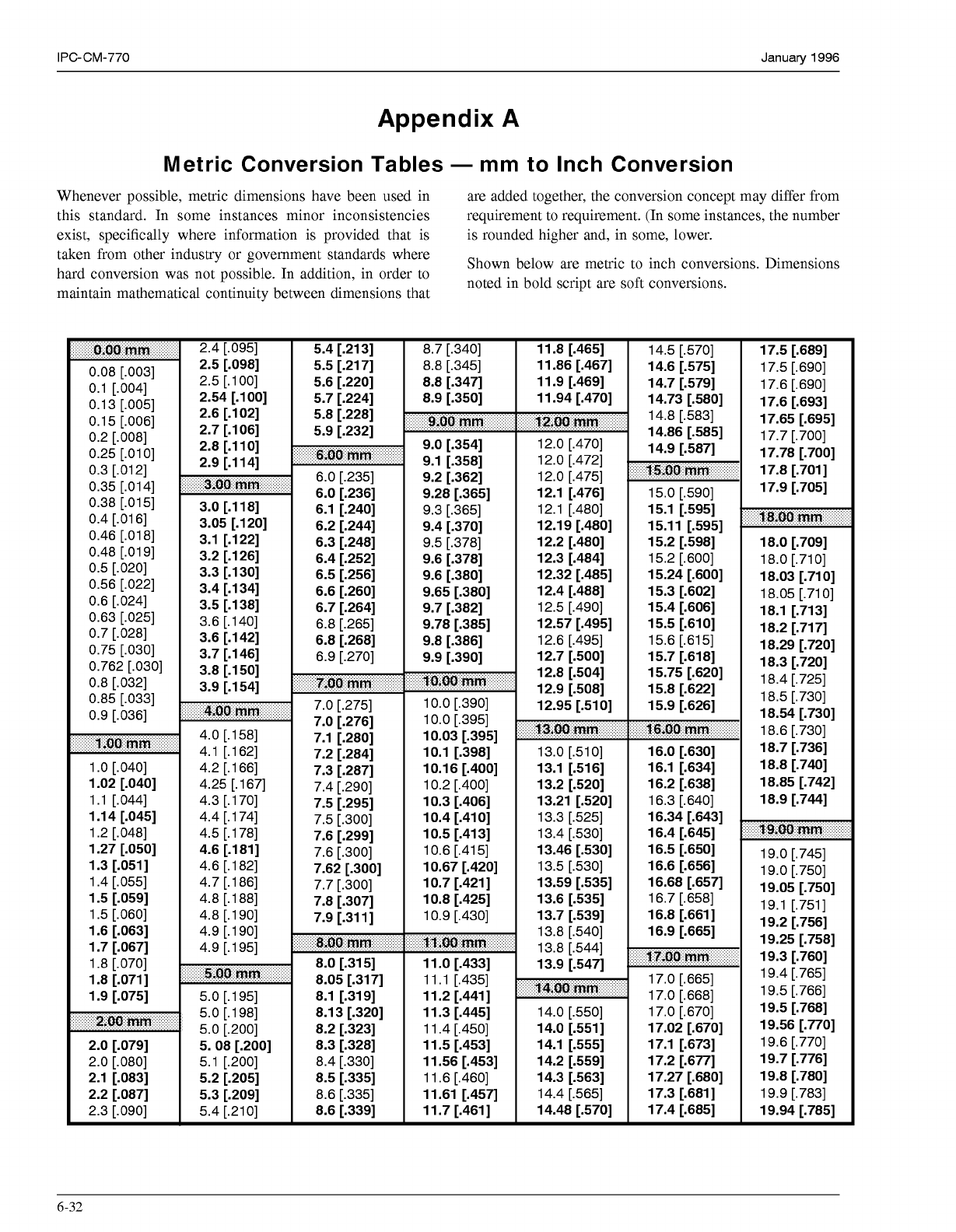
Figure 30-9 Hot Gripper
-
Hand Force Component
Remover
CAUTION: This method provides some improvement over
the Hot Gripper since it utilizes more sensitive finger tip
gripping, but still depends upon the sensitivity of the indi-
vidual. Like the hot gripper, the thermal tweezers are nor-
mally used to remove chip resistors and capacitors (or
other small two terminal components), and should be lim-
ited to removing multileaded components having less than
twenty leads.
30.6.5 Through-Hole and Surface Mounted Component
Removal
The following are the general methods for the
I
Figure 30-10 Thermal Tweezer -Finger Tip Controlled
Component Remover
removal of components or solder from solder joints on/in
printed board structures. These methods include component
removal and/or replacement of through board (standard
components, dual-inline packs, and pin-grid arrays) and
surface mounted devices.
30.6.5.1 Wicking Method
The wicking method incorpo-
rates either stranded copper wire or a braid saturated with
flux, which is then applied between the solder to be
removed and a hot soldering iron.
CAUTION: The wicking method is only recommended for
surface solder joints and is not recommended for use on
plated through hole solder joints.
30.6.5.2 Impulse Solder Sucker Method
The impulse
solder sucker method employs a single pulse vacuum gen-
erating device utilizing a squeeze bulb or a spring operated
plunger mechanism with a Teflon orifice through which the
vacuum is applied to the solder to remove it from the joint.
CAUTION: This method will not consistently remove sol-
der from plated through holes and frequently the compo-
nent lead will resweat to the plated through hole wall.
30.6.5.3 Soldering Iron SolderlSolder Method
The sol-
dering irodsolder sucker combination method is a hollow
tipped soldering iron combined with an impulse solder
sucker mechanism.
CAUTION: This method will not consistently remove sol-
der from plated through-holes and frequently the compo-
nent lead will resweat to the plated through hole wall.
30.6.5.4 Heat-and-Pull Method
The heat-and-pull meth-
ods essentially involve heating the solder joint(s) by one of
several different methods and pulling the component
lead(s) out of the solder connection.
CAUTION: The heat-and-pull methods must be used with
caution on surface mount components and are generally not
recommended for the component removal of multileaded
components with through board solder joints.
6-30
COPYRIGHT Association Connecting Electronics Industries
Licensed by Information Handling Services
COPYRIGHT Association Connecting Electronics Industries
Licensed by Information Handling Services
January
1996
IPC-CM-770
30.6.5.5 Combination Methods
These solder extraction
methods provide controlled combinations of heat, pressure,
vacuum, and airflow for the controlled removal of any sol-
der joint configuration. Advantages: This solder removal
method is easily manipulated, fully controllable and allows
a trained and skilled operator to easily remove solder and
components from most types of assemblies.
A. Solder Extraction (Continuous Vacuum) This method
uses a hollow soldering iron and tip to melt the solder and
after the solder is molten, the solder is sucked out of the
solder joint by an operator controlled vacuum pump. This
method can also be used for clinched leads, blindhlocked
holes, and auxiliary heating.
B.
Solder Extraction (Pressure Mode) This method uses a
hollow soldering iron and tip to melt the solder and after
the solder is molten, to blow it out of the solder joint by an
operator controlled vacuudpressure pump. This solder
extractor pressure method is suitable for removing solder
from blind or blocked component lead mounting holes.
30.6.5.6 Clip-and-Fix Method
In the clip-and-fix
method, the component leads of the component to be
removed are cut
off
at (or near) the component body. This
is generally not performed when the component to remove
is thought to be good. In some cases it may be desirable to
remove individual component leads with a small jet of hot
air. After solder melt the component lead is lifted
off
the
land.
30.6.6 Replacement of Surface Mounted Devices
The
general requirements and procedures for surface mounted
components are in IPC-A-610.
Prior to replacement, the surface mount component and the
land patterns on the printed board structure may have to be
hot air leveled, or pretinned and fluxed. The component
must then be precisely positioned on the land pattern and
stabilized (held in place) during solder reflow and cool
down.
CAUTION: Hot air leveling can cause undesirable over-
heating of the component, adjacent components, solder
joints, and the printed board structure.
It is not recommended, but hand soldering replacement
with a microscope aid can be successful.
6-3
1
COPYRIGHT Association Connecting Electronics Industries
Licensed by Information Handling Services
COPYRIGHT Association Connecting Electronics Industries
Licensed by Information Handling Services
IPC-CM-770
Januaty
1996
Appendix A
Metric Conversion Tables
-
mm
to Inch Conversion
Whenever possible, metric dimensions have been used in are added together, the conversion concept may differ from
this standard. In some instances minor inconsistencies requirement to requirement. (In some instances, the number
exist, specifically where information is provided that is is rounded higher and, in some, lower.
taken from other industry or government standards where
hard conversion was not possible. In addition, in order to
maintain mathematical continuity between dimensions that
Shown below are metric to inch conversions. Dimensions
noted in bold script are soft conversions.
o.06
mm
0.08 [.O031
0.1 [.O041
0.1 3 [.O051
0.1
5
[.O061
0.2 [.O081
0.25
[.O1
O]
0.3
[.O1
21
0.35
[.O1
41
0.38
[.O1
51
0.4
[.O1
61
0.46
[.O1
81
0.48
[.O1
91
0.5
[.O201
0.56 [.O221
0.6 [.O241
0.63 [.O251
0.7 [.O281
0.75 [.O301
0.762 [.O301
0.8 [.O321
0.85 [.O331
0.9 [.O361
l.0Q
mm
1
.O
[.O401
1
.O2 [.O401
1.1
[.O441
1.1
4 [.O451
1.2 [.O481
1.27 [.O501
1.3 [.O511
1.4 [.O551
1.5 [.O591
1.5 [.O601
1.6 [.O631
1.7 [.O671
1.8 [.O701
1.8 [.O711
1.9 [.O751
2.00
mm
2.0 [.O791
2.0 [.O801
2.1 [.O831
2.2 [.O871
2.3 [.O901
2.4 [.O951
2.5 [.O981
2.5
[.loo]
2.54 [.loo]
2.6 [.l O21
2.7 [.l O61
2.8 [.11 O]
2.9 [.114]
3-06
mm
3.0 [.118]
3.05 [.120]
3.1 [.122]
3.2 [.126]
3.3 [.130]
3.4 [.134]
3.5 [.138]
3.6 [.140]
3.6 [.142]
3.7 [.146]
3.8 [.150]
3.9 [.154]
4,QO
mm
4.0
[.
1581
4.1 [.162]
4.2
[.
1661
4.25
[.
1671
4.3
[.
1701
4.4 [.174]
4.5
[.
1781
4.6 [.181]
4.6
[.
1821
4.7 [.186]
4.8 [.188]
4.8 [.190]
4.9 [.190]
4.9
[.
1951
5.QO
mm
5.0
[.195]
5.0
[.198]
5.0
[.200]
5. 08 [.200]
5.1 [.200]
5.2 [.205]
5.3 [.209]
5.4 [.21
O]
5.4 [.213]
5.5 [.217]
5.6 [.220]
5.7 [.224]
5.8 [.228]
5.9 [.232]
6,OQ
mm
6.0 [.235]
6.0 [.236]
6.1 [.240]
6.2 [.244]
6.3 [.248]
6.4 [.252]
6.5 [.256]
6.6 [.260]
6.7 [.264]
6.8 [.265]
6.8 [.268]
6.9 [.270]
3.06
mm
7.0 [.275]
7.0 [.276]
7.1 [.280]
7.2 [.284]
7.3 [.287]
7.4 [.290]
7.5 [.295]
7.5 [.300]
7.6 [.299]
7.6 [.300]
7.62 [.300]
7.7 [.300]
7.8 [.307]
7.9 [.311]
8,QO
mm
8.0 [.315]
8.05 [.317]
8.1 [.319]
8.1 3 [.320]
8.2 [.323]
8.3 [.328]
8.4 [.330]
8.5 [.335]
8.6 [.335]
8.6 [.339]
8.7 [.340]
8.8 [.345]
8.8 [.347]
8.9 [.350]
9.00
mm
9.0 [.354]
9.1 [.358]
9.2 [.362]
9.28 [.365]
9.3 [.365]
9.4 [.370]
9.5 [.378]
9.6 [.378]
9.6 [.380]
9.65 [.380]
9.7 [.382]
9.78 [.385]
9.8 [.386]
9.9 [.390]
1
Q,OO
mm
10.0 [.390]
10.0 [.395]
10.03 [.395]
10.1 [.398]
10.1 6 [.400]
10.2 [.400]
10.3 [.406]
10.4 [.41 O]
10.5 [.413]
10.6 [.415]
10.67 [.420]
10.7 [.421]
10.8 [.425]
10.9 [.430]
If,#Q
mm
11
.O
[.433]
1
l.
1
[.435]
11.2 [.441]
11.3 [.445]
11.4 [.450]
11.5 [.453]
11.56 [.453]
11.6 [.460]
11.61 [.457]
11.7 [.461]
11.8 [.465]
11.86 [.467]
11.9 [.469]
11.94 [.470]
I
2.00
mm
12.0 [.470]
12.0 [.472]
12.0 [.475]
12.1 [.476]
12.1 [.480]
12.1 9 [.480]
12.2 [.480]
12.3 [.484]
12.32 [.485]
12.4 [.488]
12.5 [.490]
12.57 [.495]
12.6 [.495]
12.7 [.500]
12.8 [.504]
12.9 [.508]
12.95 [.51 O]
13.00
mm
13.0 [.51
O]
13.1 [.516]
13.2 [.520]
13.21 [.520]
13.3 [.525]
13.4 [.530]
13.46 [.530]
13.5 [.530]
13.59 [.535]
13.6 [.535]
13.7 [.539]
13.8 [.540]
13.8 [.544]
13.9 [.547]
I
4.~0
mm
14.0 [.550]
14.0 [.551]
14.1 [.555]
14.2 [.559]
14.3 [.563]
14.4 [.565]
14.48 [.570]
14.5 [.570]
14.6 [.575]
14.7 [.579]
14.73 [.580]
14.8 [.583]
14.86 [.585]
14.9 [.587]
f5AO
mm
15.0 [.590]
15.1 [.595]
15.1
1
[.595]
15.2 [.598]
15.2 [.600]
15.24 [.600]
15.3 [.602]
15.4 [.606]
15.5 [.610]
15.6 [.615]
15.7 [.618]
15.75 [.620]
15.8 [.622]
15.9 [.626]
16.00
mm
16.0 [.630]
16.1 [.634]
16.2 [.638]
16.3 [.640]
16.34 [.643]
16.4 [.645]
16.5 [.650]
16.6 [.656]
16.68 [.657]
16.7 [.658]
16.8 [.661]
16.9 [.665]
IT.W
mm
17.0 [.665]
17.0 [.668]
17.0 [.670]
17.02 [.670]
17.1 [.673]
17.2 [.677]
17.27 [.680]
17.3 [.681]
17.4 [.685]
17.5 [.689]
17.5 [.690]
17.6 [.690]
17.6 [.693]
17.65 [.695]
17.7 [.700]
17.78 [.700]
17.8 [.701]
17.9 [.705]
18.00
mm
18.0 [.709]
18.0 [.71
O]
18.03 [.71 O]
18.05 [.71
O]
18.1 [.713]
18.2 [.717]
18.29 [.720]
18.3 [.720]
18.4 [.725]
18.5 [.730]
18.54 [.730]
18.6 [.730]
18.7 [.736]
18.8 [.740]
18.85 [.742]
18.9 [.744]
19.00
mm
19.0 [.745]
19.0 [.750]
19.05 [.750]
19.1 [.751]
19.2 [.756]
19.25 [.758]
19.3 [.760]
19.4 [.765]
19.5 [.766]
19.5 [.768]
19.56 [.770]
19.6 [.770]
19.7 [.776]
19.8 [.780]
19.9 [.783]
19.94 [.785]
6-32
COPYRIGHT Association Connecting Electronics Industries
Licensed by Information Handling Services
COPYRIGHT Association Connecting Electronics Industries
Licensed by Information Handling Services