DuraBlue II Customer Product Manual.pdf - 第30页
Installation 3-2 Part 1126931_01 2018 Nordson Corporation Installation Tasks The installation sequence is as follows: 1. Verify that the required environmental conditions and utilities exist. 2. Unpack and inspect the …

Installation
3-1
Part 1126931_01
2018 Nordson Corporation
Section 3
Installation
WARNING! Allow only qualified personnel to perform the following tasks.
Follow the safety instructions in this document and all other related
documentation.
Overview
DuraBlue‐II adhesive melters are factory‐configured for each order and
require only the assembly and set up tasks described in this section.
The melter is shipped from the factory with an installation kit that contains
components that must be assembled onto the melter by the customer. Some
additional materials must also be supplied by the customer to complete the
installation.
If optional equipment was ordered with the melter, refer to the documentation
provided with the optional equipment for installation and operating
instructions.
The illustrations accompanying the procedures in this section depict a
dual‐motor dual‐stream melter.
Additional Information
This section presents installation procedures in their most commonly used
form. Procedural variations or special considerations are explained in the
additional information table that follows most procedures. Where applicable,
some table entries also contain cross‐reference information. Additional
information tables are indicated by the symbol shown to the left.

Installation
3-2
Part 1126931_01
2018 Nordson Corporation
Installation Tasks
The installation sequence is as follows:
1. Verify that the required environmental conditions and utilities exist.
2. Unpack and inspect the melter.
3. Configure the electrical service.
4. Connect hot melt hoses and applicators.
5. (Optional) Configure key-to-line.
6. (Optional) Connect to the pressure control transducer.
7. Set up the melter to work with the manufacturing process.
8. (Optional) Install inputs and outputs.
9. Install optional equipment.
10. Connect an applicator driver, pattern controller, or timer.
11. Flush the melter.
Experience of Installation Personnel
The instructions provided in this section are intended to be used by
personnel who have experience in the following subjects:
Hot melt application processes
Industrial power and control wiring
Industrial mechanical installation practices
Basic process control and instrumentation
Installation Requirements
Before installing the melter, ensure that the desired installation location
provides the required clearances, environmental conditions, and utilities.
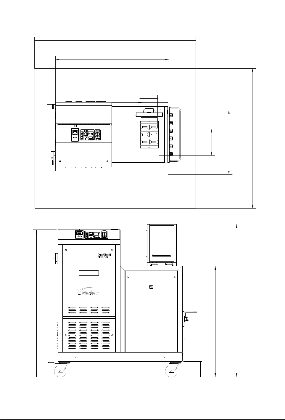
Clearances
Figure 3‐1 illustrates the minimum clearances that are required between the
melter and surrounding objects.
Installation
3-3
Part 1126931_01
2018 Nordson Corporation
Minimum Installation Clearances
118 in. (3000 mm)
41.5 in. (1054.5 mm)
6.6 in.
(167 mm)
38.3 in.
(973 mm)
23.6 in.
(600 mm)
9.7 in.
(247 mm)
38.3 in. (973 mm)
102 in. (2600 mm)
1278 in. (50.3 mm)
36.5 in. (928 mm)
48.4 in. (1230 mm)
39.2 in.
(1000 mm)
5.1 in.
(130 mm)
39.2 in.
(1000 mm)
OPERATION SPACE
OPERATION SPACE
Figure 3‐1 Melter minimum installation clearances