DuraBlue II Customer Product Manual.pdf - 第37页
Installation 3-9 Part 1126931_01 2018 Nordson Corporation Connecting Hoses and Applicators WARNING! Risk of fire or equipment damage. Before connecting hoses and applicators to the melter, confirm that the power requir…

Installation
3-9
Part 1126931_01
2018 Nordson Corporation
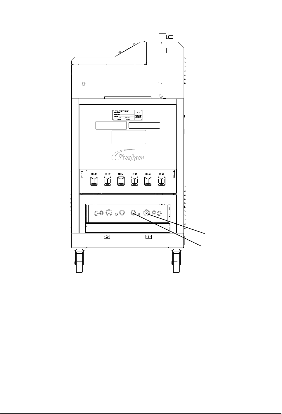
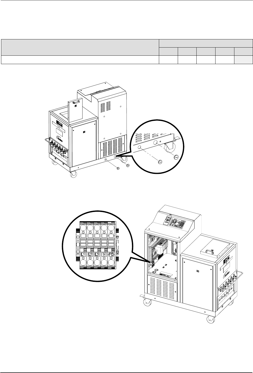
Connecting Hoses and Applicators
WARNING! Risk of fire or equipment damage. Before connecting hoses and
applicators to the melter, confirm that the power required by each
hose/applicator pair and each hose/applicator module, does not exceed the
maximum wattages specified in Appendix A, Table A‐2, Maximum Allowable
Wattages.
Connect Hoses
See Figure 3‐4 to properly connect the hose hydraulic fittings based on the
manifold configuration. If hoses are not connected properly, the melter will
not operate correctly.
See Figure 3‐5 to connect hose cordsets.
Observe the following guidelines:
For information about choosing the correct Nordson hot melt hose for
your manufacturing process, refer to the latest edition of Nordson's hot
melt dispensing equipment Replacement Parts Catalog or contact your
Nordson representative.
Refer to the user's guide provided with each Nordson hose. The guide
contains important information about routing and installing the hose.
Save all of the port plugs removed from the manifold. A port plug will
need to be reinstalled into the manifold if a hose is later removed.