DuraBlue II Customer Product Manual.pdf - 第79页
Clear/Reset key Operation 4-17 Part 1126931_01 2018 Nordson Corporation Monitor the Service Interval The melter can be set up so that the service LED located on the left side of the control panel turns on after a custo…
Operation
4-16
Part 1126931_01
2018 Nordson Corporation
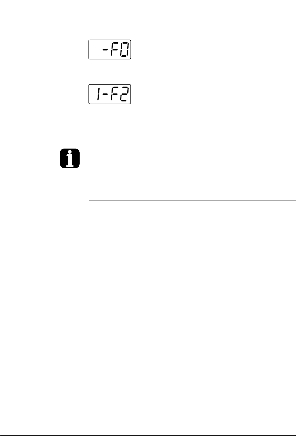
Fault Log examples
Example 1:
An unused log entry.
Example 2:
If the LED on the tank key were on, this log entry
would indicate that the tank is under temperature. If the LED on the hose key
were on, this log entry would indicate that hose 1 is under temperature.
To view the number of heater hours that have
elapsed since a log entry was created,
simultaneously press both of the right‐display
scroll keys. The hours are indicated in the right
display.
The melter will return to the automatic scan mode
if the fault log is left open for a period of two
minutes without any key being pressed.
When an F1 fault is the result of a
hose/applicator pair being disconnected from the
melter, two fault log entries are created. The first
entry is for the applicator and the second entry is
for the hose.
Clear/Reset key
Operation
4-17
Part 1126931_01
2018 Nordson Corporation
Monitor the Service Interval
The melter can be set up so that the service LED located on the left side
of the control panel turns on after a customer‐defined time period has
elapsed. The service LED may be used to signal the need to change the
hot melt filter or to complete any other customer‐specified maintenance
activity. Once the specified maintenance is performed, the service LED must
be reset.
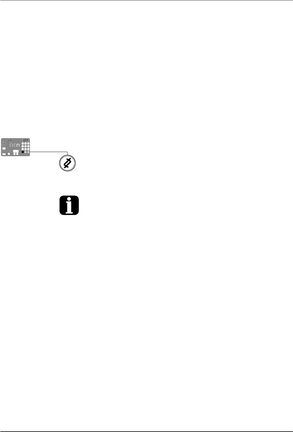
To reset the service LED
With the melter in the scan mode, press the Clear/Reset key to turn off the
service LED and reset the service interval time.
The default setting for the service interval time is 500 hours, refer to Parameter 5 in
Appendix B.
Tank key
Left display and
scroll key
Enter key
Ready LED
Operation
4-18
Part 1126931_01
2018 Nordson Corporation
Adjusting Component Temperatures
You can adjust the set‐point temperature of heated components using the
following methods:
Global—The tank and all hoses and applicators are set to the same
set‐point temperature.
Global‐by‐component group—All of the hoses or all of the
applicators are set to the same set‐point temperature.
Individual Component—The set‐point temperature of the tank
and each hose and applicator is adjusted independently.
Before adjusting set‐point temperatures, confirm that each hose/applicator
pair is connected to the correct hose/applicator receptacle. For example,
hose/applicator pair 1 should be connected to the receptacle 1. Refer to
Heated Components earlier in this section for information about
hose/applicator positions.
NOTE: For additional temperature control features, refer to
Parameters20-29 in Appendix B, Operating Parameters.
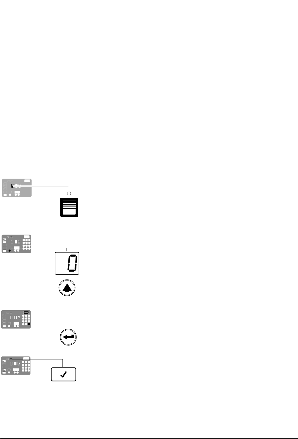
To adjust the setpoint temperature using the global method
1. Press and hold the Tank key for three seconds.
The left display flashes 1.
2. Scroll the left display to 0 (flashing).
The right display indicates all dashes (‐‐‐‐) and the LEDs on all of
the component keys turn green.
3. Press the Enter key.
The right display flashes.
4. Use the keypad to enter the set‐point temperature recommended by
the manufacturer of the hot melt.
NOTE: If the keypad or the right‐display scroll keys have no affect on the
right display, the melter is password protected. You must enter a valid
password before you can change set‐point temperatures. Refer to
Entering a Password in this section.
5. Press the Tank key.
All components begin to heat or cool to the new global
set‐point temperature. When all of the components reach their
set‐point temperature, the ready LED turns on (green).