Nordson_EFD_Automated_Dispensing_Systems_Maintenance_Guide.pdf - 第16页
Automated Dispensing Systems Maintenance & Parts Guide 16 www.nordsonefd.com info@nordsonefd.com +1-401-431-7000 Sales and service of Nordson EFD dispensing systems are available worldwide. Timing Belt T ension Adjus…
15www.nordsonefd.com info@nordsonefd.com +1-401-431-7000 Sales and service of Nordson EFD dispensing systems are available worldwide.
Automated Dispensing Systems Maintenance & Parts Guide
Component Replacement
This section provides replacement procedures for the robot timing belt, motor, and fuse. These components do not
have a replacement schedule and only require replacement in the unlikely event of damage or breakage.
7
2
3
4
1
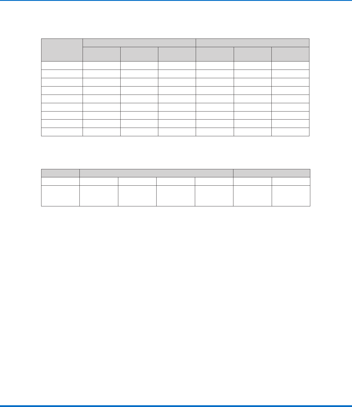
Timing Belt Tension Adjustment
The X and Yaxis timing belts require a specific tension, which is measured using a belt tension meter. The meter
works by analyzing the harmonic characteristics of a vibrating belt. Use of the tension meter requires the input of
the belt mass, belt width, and span length; these values are provided on page16. Perform the following steps
whenever you need to adjust the tension for a timing belt.
NOTE: This procedure is repeated where applicable in the component replacement procedures.
1. Enter the timing belt mass, width, and span (length) into the tension meter. Refer to “Timing Belt Mass, Width,
and Span Data” on page16 for these values.
2. Hold the meter 20 mm (0.8") from the timing belt, then strum the belt (as if it were a guitar string).
3. Observe the measurement displayed on the meter:
• If the tension is within 50–70 N•m (37–52ft‑lb), the tension is correct
• If the tension is outside 50–70 N•m (37–52ft‑lb), adjust the timing belt adjusting kit base screw and repeat
the tension measurement. Repeat as needed until the tension measures 50–70 N•m (37–52ft‑lb).
NOTE: The tension meter displays measurements only as Newtons.
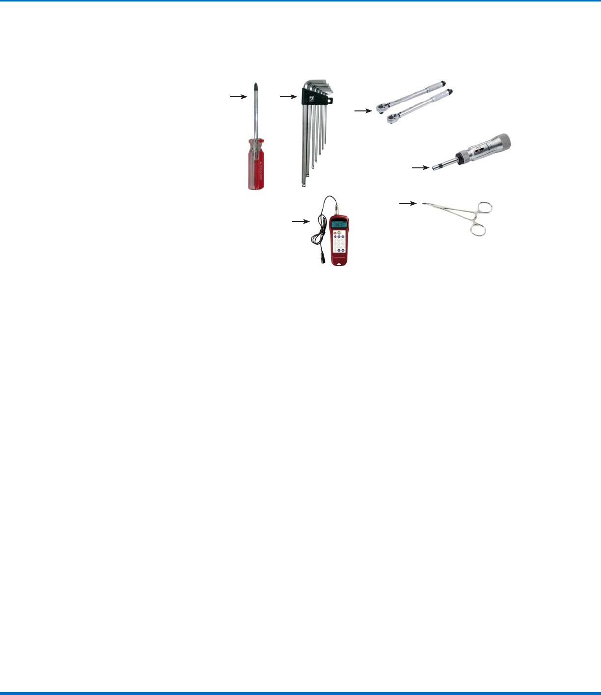
9
Tools and Supplies
1 Cross‑head screwdriver set
2 L‑style hex wrench set
3 Torque wrench
4 Torque screwdriver
5 Needle‑nose pliers (not shown)
6 Diagonal cutting pliers (not shown)
7 Belt tension meter (Nordson EFD
recommends the Gates 508C Sonic
Tension Meter)
8 Cable ties (not shown)
9 Needle‑nose pliers or fine hemostat (for
microfuse replacement
(Not shown) Replacement parts as needed
(refer to “Replacement Parts” on page38
for part numbers).
Automated Dispensing Systems Maintenance & Parts Guide
16 www.nordsonefd.com info@nordsonefd.com +1-401-431-7000 Sales and service of Nordson EFD dispensing systems are available worldwide.
Timing Belt Tension Adjustment (continued)
Timing Belt Mass, Width, and Span Data
Model
X Axis Y Axis
Mass
(g/m)
Width
(mm/R)
Span
(mm)
Mass
(g/m)
Width
(mm/R)
Span
(mm)
E2 1.3 9 289 1.3 9 289
E3 1.3 9 405 1.3 9 405
E4 1.3 9 502 1.3 9 502
E6 1.3 12 605 1.3 12 605
E6 1.3 12 722 1.3 12 605
R3 / R3V 1.3 9 405 1.3 9 405
R4 / R4V 1.3 9 502 1.3 9 502
R6 / R6V 1.3 12 722 1.3 12 605
PROPlus / PRO 1.3 12 533 1.3 12 514
Screw Torque Specifications
Refer to these torque specifications as needed.
Screw Type Hex Cross‑Truss
Size M3 M4 M5 M6 M3 M4
Torque
3.9 N•m
(40 kgf/cm)
(34.5 in.‑lb)
5.9 N•m
(60 kgf/cm)
(52.2 in.‑lb)
7.8 N•m
(80 kgf/cm)
(69.0 in.‑lb)
11.8 N•m
(120 kgf/cm)
(104.4 in.‑lb)
1.2 N•m
(12 kgf/cm)
(10.6 in.‑lb)
1.6 N•m
(16 kgf/cm)
(12.2 in.‑lb)
17www.nordsonefd.com info@nordsonefd.com +1-401-431-7000 Sales and service of Nordson EFD dispensing systems are available worldwide.
Automated Dispensing Systems Maintenance & Parts Guide
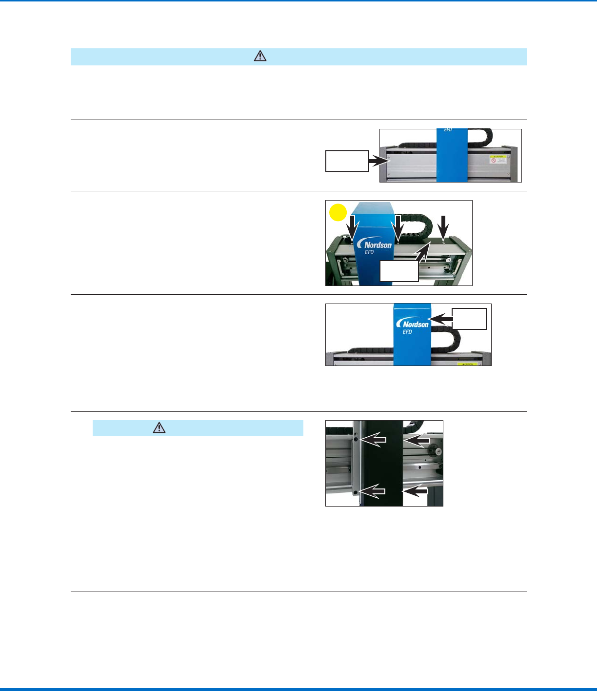
Timing Belt and Motor Replacement: XAxis
CAUTION
Risk of injury or equipment damage. Before performing any service procedure, complete the steps under
“Preparation for all Service Procedures” on page3.
Remove the X and ZAxis Covers
1
Remove the Xaxis front cover. Refer to
“Remove the XAxis Front Cover” on page4
as needed for detailed instructions.
Xaxis front
cover
2
a. Remove the six (6) screws that secure the
black Xaxis rear cover: three (3) on the top
and three (3) on the bottom.
b. Remove the Xaxis rear cover by pulling in
the Ydirection away from the back of the
robot.
a
Xaxis rear
cover
3
Remove the Zaxis cover. Refer to the following
procedures as needed for detailed instructions:
• “Remove the ZAxis Cover (All Units Except
R / RV Series)” on page8
• “Remove the ZAxis Cover (R / RV Series
Only)” on page10
Zaxis
cover
Replace the XAxis Timing Belt
4
CAUTION
Risk of equipment damage or personal injury. The
Zaxis module is heavy and will fall if not held.
Nordson EFD recommends that the Zaxis module be
held by an assistant during disassembly.
Tightly grasp the Zaxis module and then
remove the four (4) screws on the left and right
sides of the Zaxis module that fasten it to the
Xaxis linear guideway.
NOTE: Nordson EFD recommends that
the Zaxis module be held by an assistant;
alternatively, you can carefully place the Zaxis
module on the top the robot in a position that
will not strain any connections.
Continued on next page