Nordson_EFD_Automated_Dispensing_Systems_Maintenance_Guide.pdf - 第38页
Automated Dispensing Systems Maintenance & Parts Guide 38 www.nordsonefd.com info@nordsonefd.com +1-401-431-7000 Sales and service of Nordson EFD dispensing systems are available worldwide. Replacement Parts • Most r…
37www.nordsonefd.com info@nordsonefd.com +1-401-431-7000 Sales and service of Nordson EFD dispensing systems are available worldwide.
Automated Dispensing Systems Maintenance & Parts Guide
2
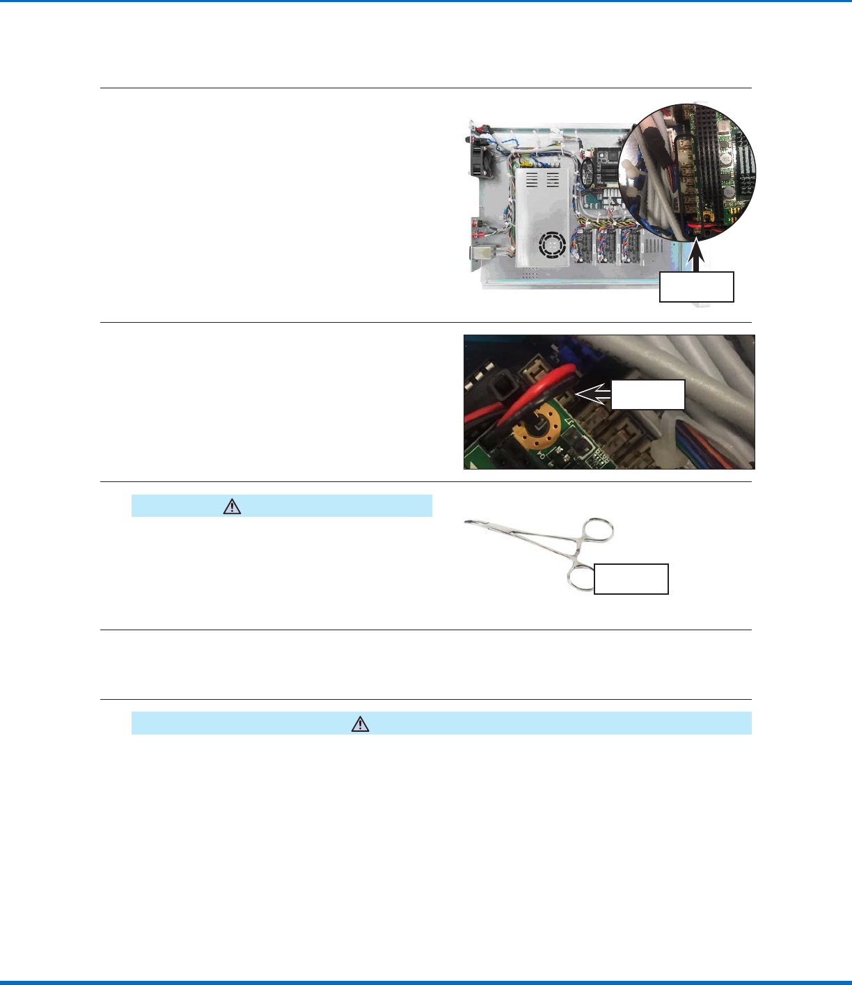
Locate the microfuses on printed circuit
boardB. The microfuses are very small.
I/O microfuses
3
Use a multimeter to check microfuse 1A (the
main output microfuse): With the multimeter
in resistance mode, touch the metal tips of
the testing leads to the metal ends of the
microfuse. If the resistance displayed does not
change (thus remaining at a 100% resistance
state), then the microfuse is blown. If a small
resistance is measured, then the microfuse is
good.
Microfuse 1A
4
CAUTION
Avoid pinching or grasping the small tabs that hold
the microfuse; doing so can permanently damage the
microfuse holder.
If the microfuse is blown, use needle‑nose pliers
or a fine hemostat to remove the microfuse and
to reinstall a replacement microfuse.
Typical
hemostat tool
5
Visually inspect the other microfuses for a broken wire or a scorched cylinder that is brown or black in
color; these are signs of a blown microfuse.
NOTE: You can also use a multimeter to check the microfuses (same instructions as in step 3).
6
CAUTION
Avoid pinching or grasping the small tabs that hold the microfuse; doing so can permanently damage the
microfuse holder.
If a microfuse is blown, use needle‑nose pliers or a fine hemostat to remove the microfuse and to
reinstall a replacement microfuse.
I/O Microfuse Replacement (continued)
Fuse Replacement (continued)
Automated Dispensing Systems Maintenance & Parts Guide
38 www.nordsonefd.com info@nordsonefd.com +1-401-431-7000 Sales and service of Nordson EFD dispensing systems are available worldwide.
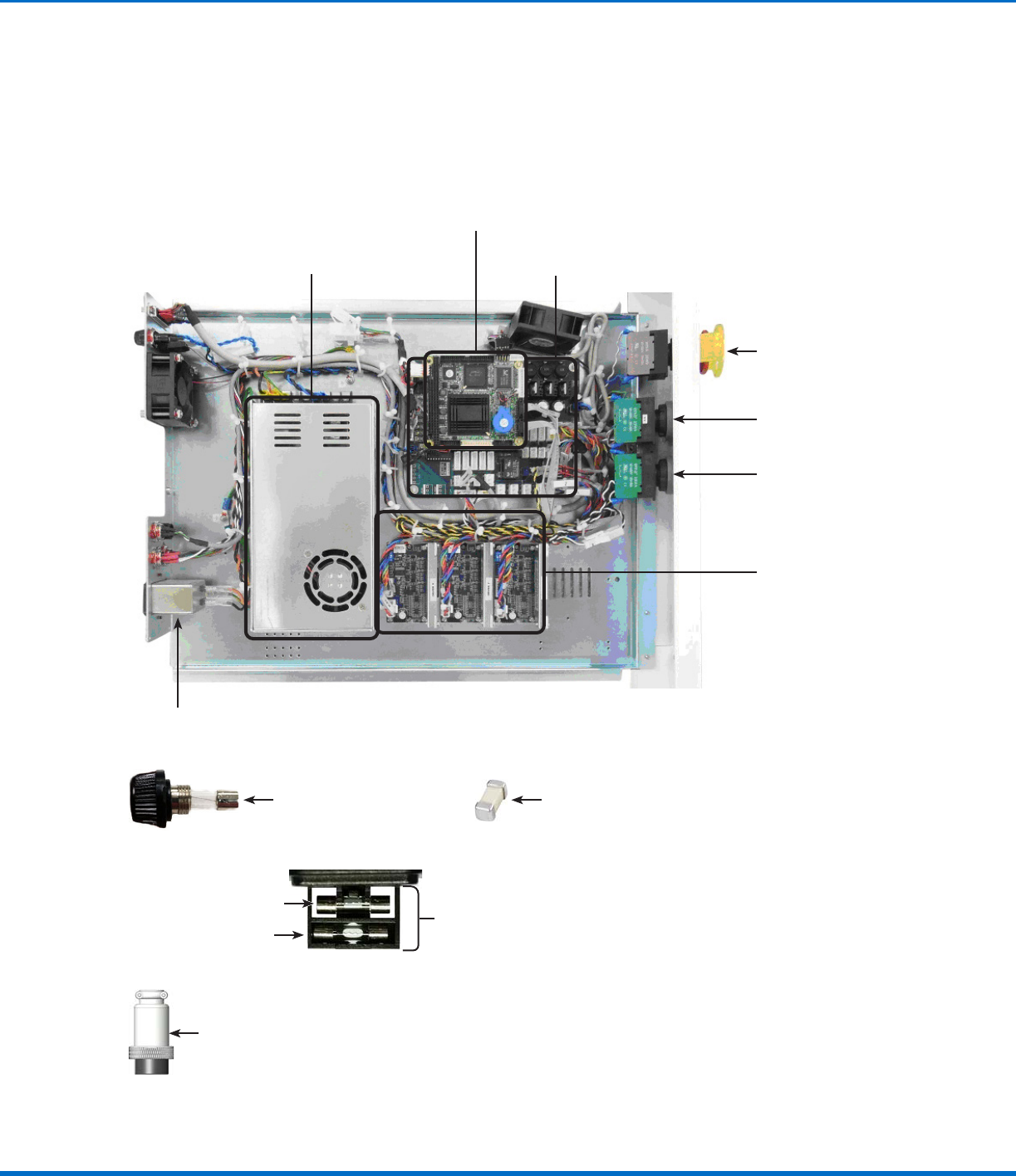
Replacement Parts
• Most replacement parts are grouped into hardware kits by robot model. Refer to “Hardware Kits” on page39.
• The printed circuit boards (PCBs) are applicable to all models and are available in a standalone kit. Refer to
“Printed Circuit Board (PCB) Kit” on page40.
• Other available kits are specific to each robot model. Refer to “Model‑Specific Kits” on page40.
Motor drive PCBs
Power supply
EMERGENCY STOP
button switch
PCB A
PCB B (the larger board under PCB A)
PURGE button switch
START button switch
Fuse, 20 mm, 4 A
Spare fuse holder
Assembly, spare fuse holder and
fuse
Microfuse, I/O, 125 mAFuse, 20 mm, 3 A
Shorted plug
Power entry
module
39www.nordsonefd.com info@nordsonefd.com +1-401-431-7000 Sales and service of Nordson EFD dispensing systems are available worldwide.
Automated Dispensing Systems Maintenance & Parts Guide
Replacement Parts (continued)
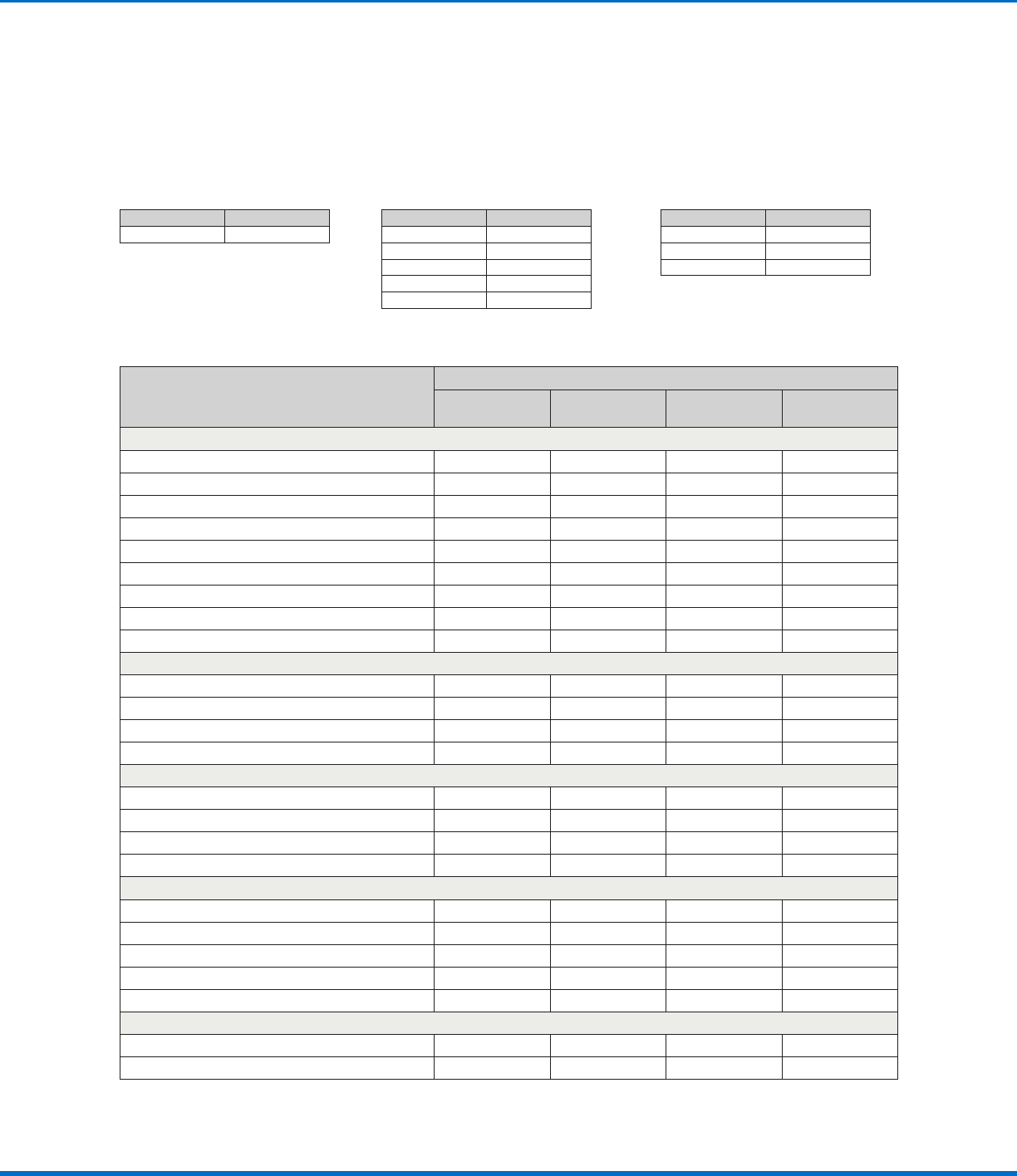
Hardware Kit Contents
Component Group
Included in the Hardware Kit for these Models
PROPlus / PRO
E2 / E2V
Only
E3–E6 / E3–E6V
(Not E2 / E2V)
R / RV
Mechanical
Hardware kit (screws for a pencil or CCD camera)
X X X
Belt kit
X X X X
Grease kit
X X X X
Motor, Z axis
X X X X
Motor, Y axis
X X X X
Motor, X axis
X X X X
Motor, R axis
X
Spring, standard
X X
Spring, 6 kg
X
Electrical Switches
START button switch
X X X X
EMERGENCY STOP button switch
X X X X
PURGE button switch
X X X X
Optical switch
X X X X
Electrical Control
Power supply, 24V, 320W
X X X X
Power entry module
X X X X
Motor drive PCBs
X X X X
Shorted plug
X X X X
Fuses
Microfuse, I/O, 125 mA
X X X X
Fuse, 20 mm, 1 A
X
Fuse, 20 mm, 3 A
X X X
Fuse, 20 mm, 4 A
X X X X
Fuse holder
X X X X
Model‑Specific
CCD camera cable
X
Replacement camera lens
X
Hardware Kits
Hardware kits vary depending on the robot model and include replacement parts that correspond to the procedures
in this manual.
Part # Model
7363278 PROPlus / PRO
Part # Model
7363275 R3 / R3V
7363276 R4 / R4V
7363277 R6 / R6V
Part # Model
7363279 E2 / E2V
7363280 E3 / E3V
7363281 E4 / E4V
7363282 E5 / E5V
7363283 E6 / E6V
Hardware Kit Part Numbers