Nordson_EFD_Automated_Dispensing_Systems_Maintenance_Guide.pdf - 第20页
Automated Dispensing Systems Maintenance & Parts Guide 20 www.nordsonefd.com info@nordsonefd.com +1-401-431-7000 Sales and service of Nordson EFD dispensing systems are available worldwide. 16 Remove the two (2) set …
19www.nordsonefd.com info@nordsonefd.com +1-401-431-7000 Sales and service of Nordson EFD dispensing systems are available worldwide.
Automated Dispensing Systems Maintenance & Parts Guide
10
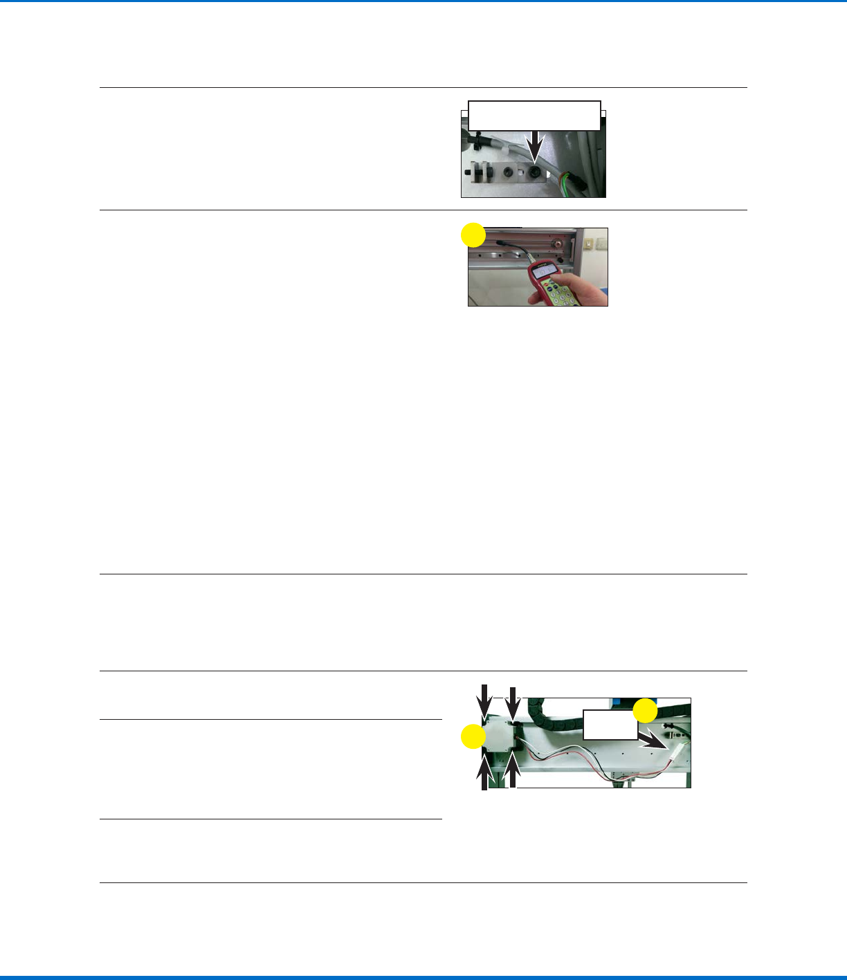
Tighten the timing belt adjusting kit base screw
on the rear of the robot Xaxis to tighten the
belt.
Timing belt adjusting kit
base screw
11
Measure the tension on the timing belt as
follows:
a. Move the Xaxis linear guideway plate to the
left‑most position.
b. Enter the timing belt mass, width, and span
(length) into the tension meter. Refer to
“Timing Belt Mass, Width, and Span Data”
on page16 for these values.
c. Hold the meter 20 mm (0.8") from the timing
belt, then strum the belt (as if it were a guitar
string).
d. Observe the measurement displayed on the
meter:
• If the tension is within 50–70 N•m
(37–52ft‑lb), the tension is correct
• If the tension is outside 50–70 N•m (37–
52ft‑lb), adjust the timing belt adjusting
kit base screw again and repeat the
tension measurement. Repeat as needed
until the tension measures 50–70 N•m
(37–52ft‑lb).
c
12
Secure the Zaxis module to the Xaxis linear guideway plate with the four (4) screws removed
previously.
Replace the XAxis Motor
13
On the rear side of the Xaxis, disconnect the
Xaxis motor cable.
Xaxis
motor cable
13
15
14
Release the Xaxis timing belt from the timing
pulley attached to the Xaxis motor.
NOTE: For detailed instructions on releasing the
timing belt, refer to “Replace the XAxis Timing
Belt” on page17.
15
Remove the four (4) screws that mount the
Xaxis motor to the robot, then pull the motor
away from the robot.
Timing Belt and Motor Replacement: XAxis (continued)
Continued on next page
Replace the XAxis Timing Belt (continued)
Automated Dispensing Systems Maintenance & Parts Guide
20 www.nordsonefd.com info@nordsonefd.com +1-401-431-7000 Sales and service of Nordson EFD dispensing systems are available worldwide.
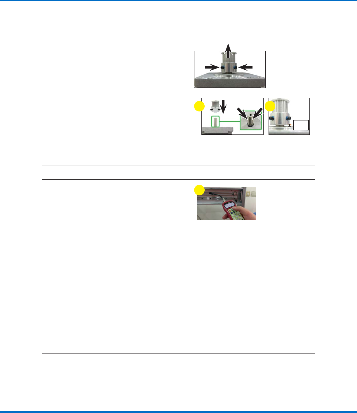
16
Remove the two (2) set screws on the timing
pulley and then pull the timing pulley away from
the motor.
17
a. Assemble the timing pulley onto the shaft of
the new motor; align the timing pulley such
that the two (2) set screws contact the two
flat surfaces of the motor shaft.
b. Ensure that the distance from the base of
the timing pulley to the top of the motor is
4mm (0.16").
4 mm
(0.16")
a b
18
Place the new Xaxis motor into position and secure it with the four (4) screws removed previously.
19
Place the Xaxis timing belt around the timing pulley.
20
Measure the tension on the timing belt as
follows:
a. Move the Xaxis linear guideway plate to the
left‑most position.
b. Enter the timing belt mass, width, and span
(length) into the tension meter. Refer to
“Timing Belt Mass, Width, and Span Data”
on page16 for these values.
c. Hold the meter 20 mm (0.8") from the timing
belt, then strum the belt (as if it were a guitar
string).
d. Observe the measurement displayed on the
meter:
• If the tension is within 50–70 N•m
(37–52ft‑lb), the tension is correct
• If the tension is outside 50–70 N•m (37–
52ft‑lb), adjust the timing belt adjusting
kit base screw again and repeat the
tension measurement. Repeat as needed
until the tension measures 50–70 N•m
(37–52ft‑lb).
c
Reinstall the XAxis Front Cover
21
Reinstall the Xaxis cover. Refer to “Reinstall the XAxis Front Cover” on page5 for detailed
instructions.
Timing Belt and Motor Replacement: XAxis (continued)
Replace the XAxis Motor (continued)
21www.nordsonefd.com info@nordsonefd.com +1-401-431-7000 Sales and service of Nordson EFD dispensing systems are available worldwide.
Automated Dispensing Systems Maintenance & Parts Guide
Timing Belt and Motor Replacement: YAxis
CAUTION
Risk of injury or equipment damage. Before performing any service procedure, complete the steps under
“Preparation for all Service Procedures” on page3.
Remove the YAxis, the Control Assembly, and the Control Assembly Cover
1
Remove the Yaxis cover. Refer to “Remove
the YAxis Cover” on page6 for detailed
instructions. Return here to continue.
2
Remove the control assembly. Refer to the
applicable steps under “Remove and Clean the
Control Assembly” on page14 to remove the
control assembly. Return here to continue.
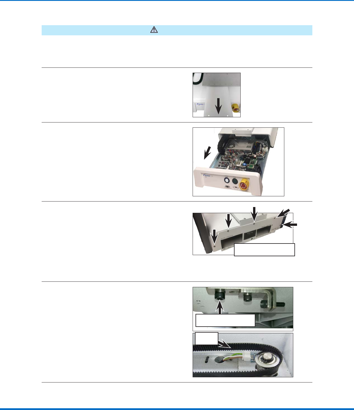
3
Remove all remaining screws on the back of the
robot that secure the control assembly cover
and then remove the cover to allow access to
the Yaxis motor.
NOTE: The quantity and location of the screws
that secure the control assembly cover differs
for each robot model.
Typical control assembly cover
screw locations
Replace the YAxis Timing Belt
4
Release the timing belt adjusting kit base screw
that sits in the front opening of the robot where
the control assembly was previously installed.
This loosens the timing belt enough to remove it
from the idler and timing pulleys.
NOTE: The screw only needs to be loosened,
not completely removed.
Loose
timing belt
Timing belt adjusting kit
base screw
Continued on next page