Specification SIPLACE CS-Speed.pdf - 第14页
12 Description Some local safety requirements dictate that all feeder l ocations must be equipped with feeder s. If the feeder set-up does not fill all feeder locations, guards ma y be used in place of the modules. SAFET…
11
Description
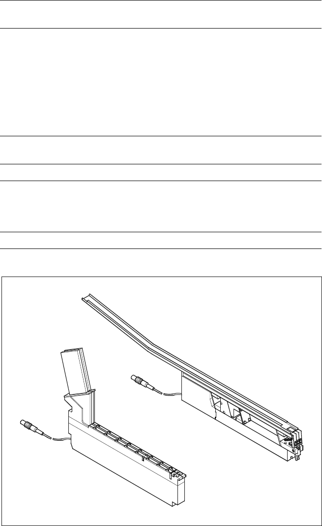
The SIPLACE Bulk Case feeder
with 2 tracks is used to handle
components packaged in standard
bulk containers. It transports rec-
tangular and cylindrical passive
components to the pick up area of
the machine. To replenish the
supply, the Bulk Cases are re-
moved and replaced outside the
machine eliminating stoppages for
replenishment.
Essentially, this feeder module
consists of a base which holds 2
feeder rails. The components are
separated and transported through
the feeder rail via compressed air.
The principle of stationary compo-
nent tables has been tried and
tested specifically with Bulk Case
components. Vibrations, which
developed when other placement
methods are used may cause
wear to the components compro-
mising quality and reliability of the
components.
The stationary component table
also brings decisive advantages for
stick magazines. The general pur-
pose vibratory stick feeder can be
refilled during the placement proc-
ess.
The feeders can be used in other
SIPLACE machines as well.
Component Supply:
Bulk Case Feeder
Stick Magazine Feeder
Technical Data
Bulk Case feeder
a
Type of packaging
Bulk Case
Feeder rails for Chip 0402 component height 0.35 mm
Chip 0402 component height 0.50 mm
Chip 0603 component height 0.45 mm
Chip 0603 component height 0.80 mm
Chip 0805 component height 0.45 mm
Chip 0805 component height 0.60 mm
Chip 0805 component height 0.85 mm
Chip 0805 component height 1.25 mm
Mini-Melf
Feeder location 1 feeder location for 2 different
component types
Stick magazine feeder Type III With control electronics
Number and width of tracks 3 x 9.5 mm
2 x 15 mm
1 x > 15 mm
1 x 30 mm
Feeder location 1
a) Fiducial to recognize position of feeder.
Bulk Case Feeder and Stick Feeders
Bulk Case Feeder
Stick Feeder
Type III
12
Description
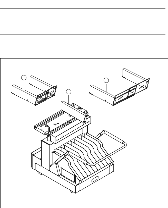
Some local safety requirements
dictate that all feeder locations
must be equipped with feeders.
If the feeder set-up does not fill all
feeder locations, guards may be
used in place of the modules.
SAFETY
WARNING
Component Supply:
Guard for Feeder Locations
The following guard-variants can be used:
1 SIPLACE guard for 1 location
2 SIPLACE guard for 6 - 10 locations
3 SIPLACE guard for 11 - 20 locations
Various Guards for Feeder Locations
3
2
1
13
Description
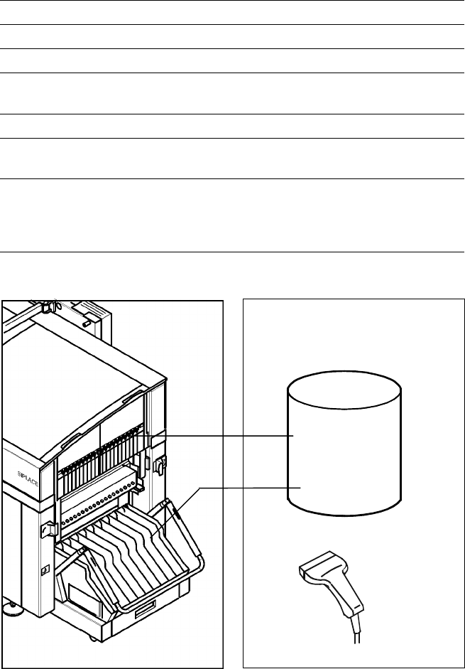
The bar code scanner enables a
quick and reliable check of com-
ponent set-up and refill. The bar
codes of the tracks and the loaded
components assigned to the
tracks (bar code labels on tapes,
Bulk Cases, etc.) are read in with
a hand scanner. An audible and
optical signal acknowledges a suc-
cessful reading operation. If the
label is damaged the bar code
can be entered at the keyboard.
The allocation of the components
to their respective track is de-
scribed in the set-up data. An error
message is displayed if the data
received from the bar code scan-
ner does not conform to the set-up
data.
If the set-up check is switched
on, it becomes a mandatory step
in the set-up process. If it is
switched off the set-up check
is optional.
Component Supply:
Component Bar Code Scanner for Set-Up and Refill Check
(Option)
Technical Data
Connection Station computer
Data input Bar code scanner or keyboard
Number of characters Max. 40
Restrictions Bar codes beginning with number 1 or 2
and with less than 5 characters
Number of bar codes Max. 6 per component
Number of filters
to extract relevant data Max. 1 per bar code
Preset code types Code 39 (standard or full ASCII),
Code 2 from 5 interleaved and normal,
Code 128, UPC/EAN/JAN codes
(more on request)
Scanner
Component
Control
Set-Up File
Track Bar Code
Scanner
Component
Bar Code
The scanner checks the corresponding track and the components