Specification SIPLACE CS-Speed.pdf - 第23页
21 1. After switching-on the station Technical Data: Signal Interfaces Signal Interface (20-Pin Ribbon C able Connector) to upstream station x3 to down stream station x4 Pin 13 GND 24 V Pin 10 R eserved Pin 14 Arrived Pi…
20
Description
Line Programming Sy
Line Programming SyLine Programming Sy
Line Programming Sys
ss
stem
temtem
tem
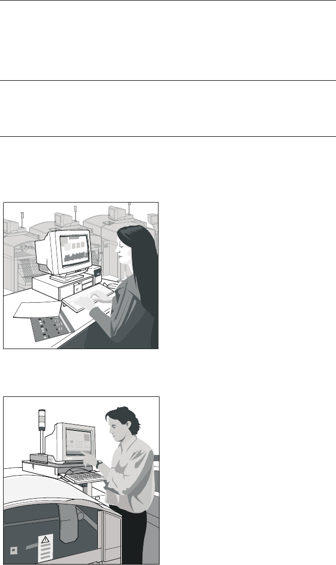
The programming System
SIPLACE C Pro, which runs on
standard PC using Windows XP
operating system, optimizes and
controls complete SIPLACE
placement lines. Consequently
secondary times are reduced and
maximum productivity is guaran-
teed. A graphical user interface
eliminates operating errors.
Station Computer
Station ComputerStation Computer
Station Computer
The station computer in conjunc-
tion with the machine controller
with its realtime capability per-
forms the following jobs: digital
control of the machine gantry
systems; control of PCB input
and output and of PCB transport;
monitoring functions, handling of
malfunctions and output of error
messages (including Help system);
ensuring the optimal quality of the
placement process.
SIPLACE Software Architecture:
Line Programming System
Station Computer
Line Programming System
Station Computer
Functions
Line Programming System for
Software
Data Preparation – Virtual Product Build
Optimization
Line control
Line monitoring
Data management
SIPLACE C Pro (Windows XP)
Station Computer for
Software
Machine control
Machine monitoring
Machine operation
SW 1.01
21
1. After switching-on the station
Technical Data:
Signal Interfaces
Signal Interface (20-Pin Ribbon Cable Connector)
to upstream station x3 to downstream station x4
Pin 13 GND 24 V Pin 10 Reserved
Pin 14 Arrived Pin 9 Reserved
Pin 15 Permission Pin 8 Reserved
Pin 19 Request Pin 4 +30 V DC
unsaturated
Pin 20 GND 24 V for request / re-
leased (contact separation)
Pin 5 GND 24 V
Pin 18 Released Pin 6 +24 V DC
Pin 12 Trouble signal loop Pin 11 Trouble signal loop
Pin 11 Pin 12
Pin 3 +24 V DC Pin 15 Permission
Pin 2 GND 24 V Pin 13 GND 24 V for per-
mission / arrived
(contact separation)
Pin 1 +30 V DC unsaturated Pin 14 Arrived
Pin 8 Reserved Pin 18 Released
Pin 9 Reserved Pin 19 Released
Pin 10 Reserved Pin 20 GND 24 V
Requirement
Delivery
Permission
Receival
Requirement
Delivery
Permission
Receival
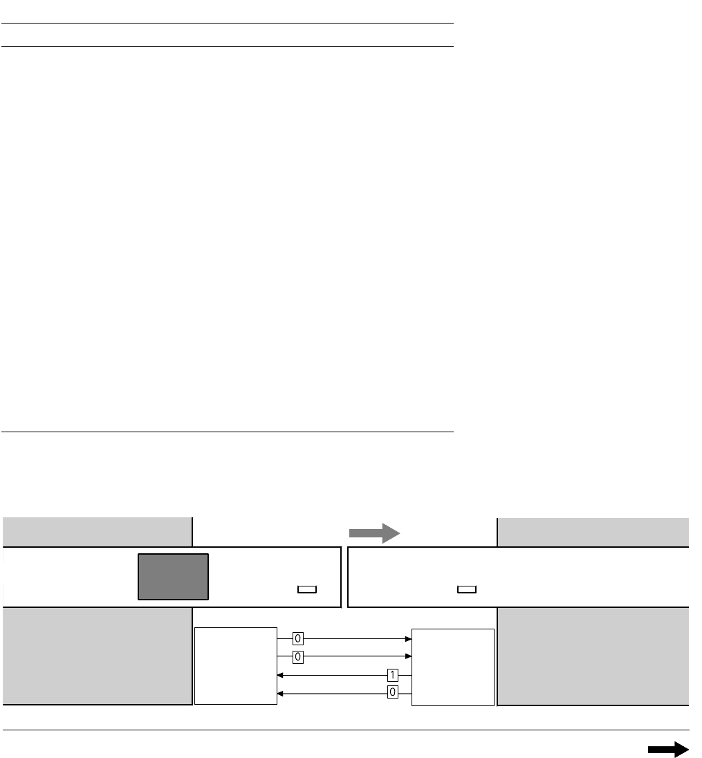
Transport Direction
Conveyor Section 1
PCB
Sensor
PCB
Sensor
Conveyor Section 2
Station n
transports
PCB
to delivery
Station n+1
is ready to
receive PCBs
Conveyor 1 is On Conveyor 2 is Off
22
Technical Data:
Signal Interfaces
2. PCB handling has started
Conveyor 1 is On Conveyor 2 is On
Transport Direction
Conveyor Section 1
Conveyor Section 2
Station n
delivers PCB
to station n+1
Station n+1
waits for PCB
from station n
Requirement
Delivery
Permission
Receival
Requirement
Delivery
Permission
Receival
PCB
Sensor
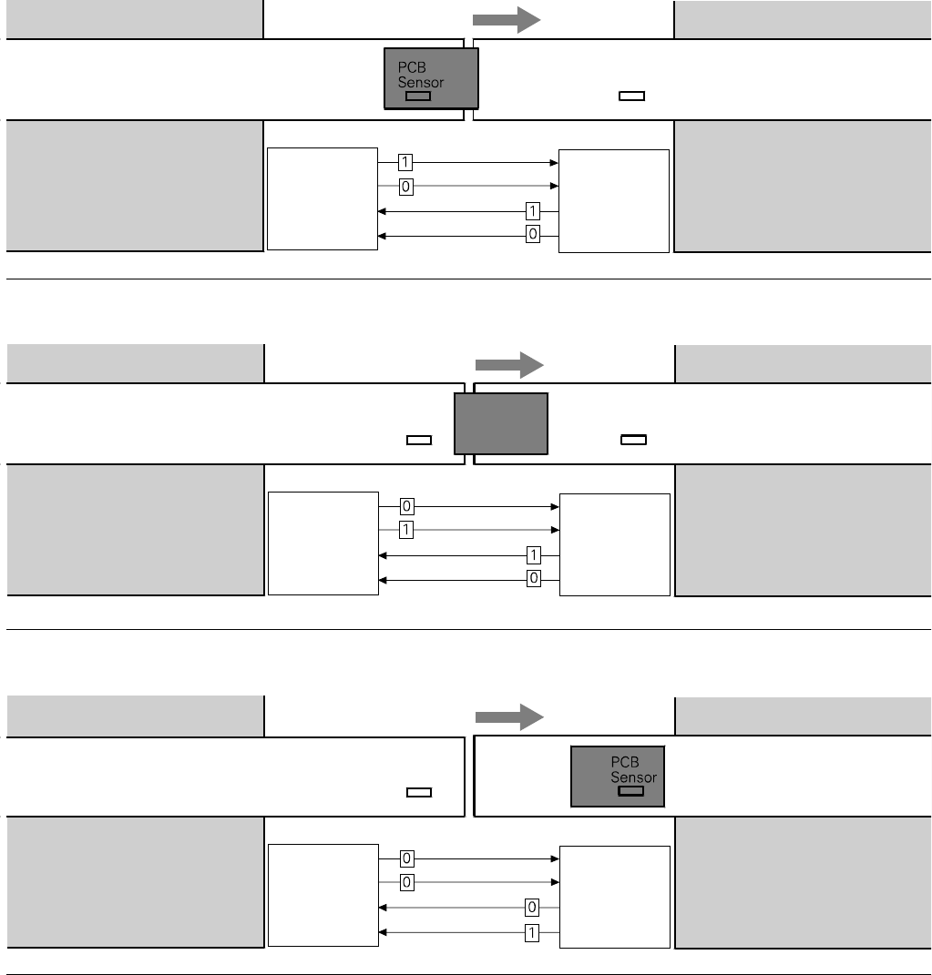
Transport Direction
Conveyor Section 1
PCB
Sensor
Conveyor Section 2
Station n
has just
delivered PCB
Station n+1
waits for PCB from
station n, but has
not received it
Requirement
Delivery
Permission
Receival
Requirement
Delivery
Permission
Receival
PCB
Sensor
3. PCB is at delivery
Conveyor 1 is Off Conveyor 2 is On
Conveyor 1 is Off Conveyor 2 is On
Transport Direction
Conveyor Section 1
PCB
Sensor
Conveyor Section 2
Station n Station n+1
has just received
the PCB
Requirement
Delivery
Permission
Receival
Requirement
Delivery
Permission
Receival
4. PCB transport is finished
A detailed documentation of the
PCB transport signal interface is
available on request.