Specification SIPLACE CS-Speed.pdf - 第9页
7 Description A nozzle changer corresponding to the Collect & Pla ce Head in u se can be installed to the left of the PCB conve yor with no loss of feeder capacity. It will cha nge the nozzle set-up of the placement …
6
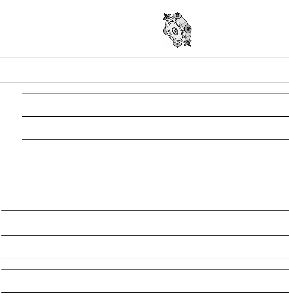
Placement Heads:
Placement Accuracy
Component Range
Placement Accuracy
a
Placement Head
Placement Accuracy
6-Nozzle
Collect & Place Head
X/Y Accuracy ± 67.5 µm
3
Sigma
Rot.-Accuracy ± 0.525°
X/Y Accuracy ± 90.0 µm
4
Sigma
Rot.-Accuracy ± 0.700°
X/Y Accuracy ± 135.0 µm
6
Sigma
Rot.-Accuracy ± 1.050°
a) As defined in Scope of Service and Delivery SIPLACE.
Component Range
6-Nozzle
Collect & Place Head
Component size
0.6 x 0.3 mm
2
b
to
18.7 x 18.7 mm
2
Max. component height 6 mm
Max. component weight 2 gr
Placement force 2.4 - 5.0 N
Performance See table on page 3
Min. pitch lead / bump 500 / 350 µm
Min. ball / bump diam. 200 µm
b) 0201 (recommended to order the special 0201-kit).
7
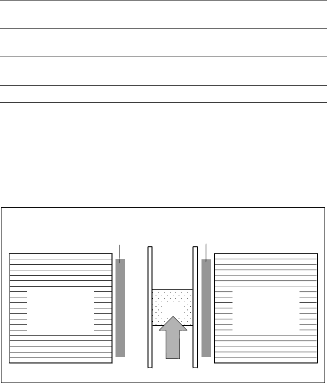
Description
A nozzle changer corresponding to
the Collect & Place Head in use
can be installed to the left of the
PCB conveyor with no loss of
feeder capacity. It will change the
nozzle set-up of the placement
head quickly and reliably for the
specific nozzle configuration valid
to a job. Damaged or faulty nozzles
can be exchanged via the menu
function on the station computer.
Placement Heads:
Nozzle Changer
Technical Data
6-Nozzle Collect & Place Head
Type of nozzle All standard nozzles of nozzle series 7xx/9xx
(special nozzles must be tested individually)
Capacity 5 magazines, each with 6 nozzles of one
nozzle series
Nozzle changing times About 2 s per nozzle
Position of Nozzle Changers
Component
Feeders for
Collect & Place
Head
PCB
Nozzle Changer for 6-Nozzle Collect & Place Head
(5 Magazines, each with 6 Nozzles, Option)
Component
Feeders for
Collect & Place
Head
8
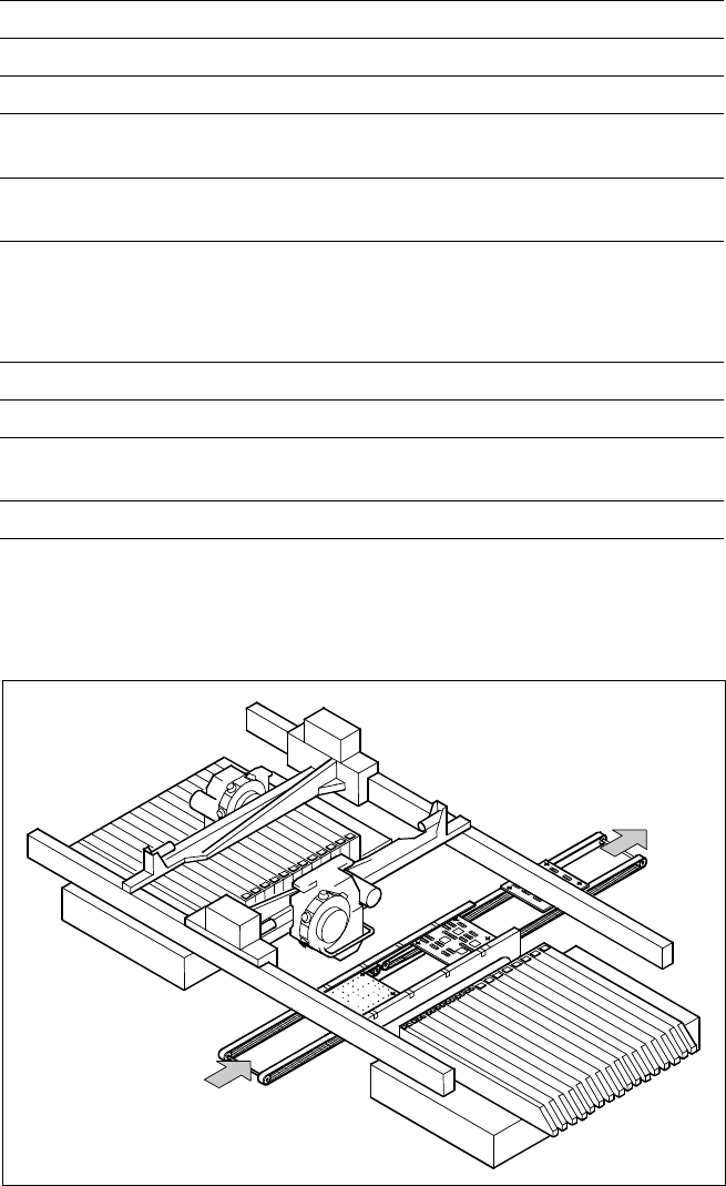
Description
On SIPLACE CS the in-line con-
veyor system guarantees a quick
adjustment to new PCB widths.
The change is made either at the
station computer using the menu
function or from the line computer
via the automatic width adjust-
ment unit.
The conveyor can be ordered with
a fixed rail on right or left.
PCB Conveyor
PCB Conveyor
PCB
Transport Direction
Technical Data
PCB dimensions See table on page 3
PCB thickness 0.5 to 4.5 mm
Max. PCB weight 3 kg
Max. PCB warpage Top: 4.5 mm - PCB thickness
Bottom: 0.5 mm + PCB thickness
Free space on PCB bottom side Standard: 25 mm,
Option: max. 40 mm
PCB conveyor height
830
± 15 mm (Standard)
900
± 15 mm (Option)
930
± 15 mm (Option)
950
± 15 mm (Option) SMEMA
Fixed conveyor edge Right (standard), left (option)
Type of interface Siemens (standard); SMEMA (option)
Component-free PCB
handling edge 3 mm
PCB loading time 2.5 s