Specification SIPLACE CS-Speed.pdf - 第20页
18 Description The standard component vision module is d irectly integr ated into the Collect & Pla ce Head. While the component is cycling into the next station of the Co llect & Place Head, the recorded im age …

17
Description
In the cluster technology each
subpanel is assigned an ink spot.
If this is present during the meas-
urement via the PCB vision mod-
ule, the corresponding subpanel is
populated. It is also possible to ac-
complish the population of the
subpanel when the ink spot is
missing. With this function it is
possible to eliminate costs due to
unnecessary population of faulty
subpanels.
Global Ink Spot
Global Ink SpotGlobal Ink Spot
Global Ink Spot
Each bad board evaluation needs
time, so naturally the consumed
time increases with the number of
subpanels per PCB. Using a global
ink spot can result in a significant
reduction of these secondary
times.
The PCB vision module searches
at positions taught before for the
defined fiducial. In case of recogni-
tion there is no following evalua-
tion of subpanels. The system al-
lows the customer to choose also
the opposite interpretation.
Position Recognition of Feeder
Position Recognition of FeederPosition Recognition of Feeder
Position Recognition of Feeder
The pick-up position of the com-
ponents can be determined pre-
cisely with the aid of the position
recognition of the feeder. It is acti-
vated each time after a change of
feeder or component table. The
offset in position relative to the
stored ideal position is determined
on the basis of fiducials on the
feeder modules using the PCB vi-
sion module. This provides a very
high pick-up reliability even for the
very first component. This is par-
ticularly important with small com-
ponents.
Vision Sensor Technology:
Bad Board Recognition
Position Recognition of Feeder
Ink Spot Criteria
Evaluation method
for fiducials
for structures
brightness method
contrast method
Shapes and sizes of
fiducials/structures for
brightness method
contrast method
square or circular forms
edge length/diameter 0.3 - 5 mm
rectangular forms
edge length 0.3 - 5 mm
Masking material mat dark (light-absorbing)
not recommended: white or shiny
Ink spot recognition time 0.3 s for each method

18
Description
The standard component vision
module is directly integrated into
the Collect & Place Head. While
the component is cycling into the
next station of the Collect & Place
Head, the recorded image is eva-
luated by the central vision sys-
tem. The component rotation is
then corrected by the appropriate
angle based on the position off-
sets determined with vision in-
spection.
Vision Sensor Technology:
Standard Component Vision Modules for the 6-Nozzle
Collect & Place Head
Standard Component Vision Module for the 6-Nozzle C & P Head
Component size
minimum
maximum
0.6 x 0.3 mm
2
(0201)
18.7 x 18.7 mm
2
Component range See table on page 6
Camera’s field of view 24 x 24 mm
2
Illumination Front light
(3 freely programmable planes)
Pixel size 50 µm
19
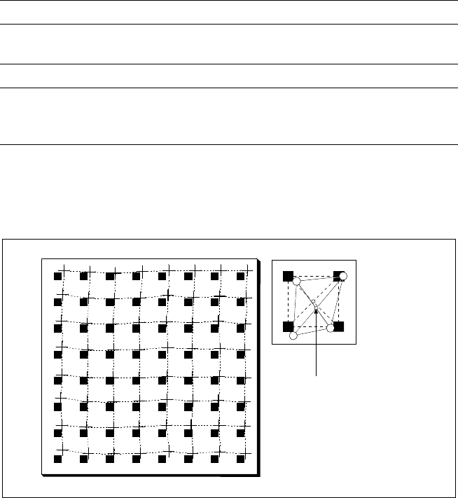
Description
Despite the highly stable machine
frame, slight distortions of the
gentry axes cannot always be
avoided. With the aid of the
mapping process the high place-
ment accuracy of the machine is
preserved throughout its entire
service life.
With this calibrating procedure,
which can be conducted quickly
and easily, the PCB camera recog-
nizes the fiducials on a mapping
calibration plate placed in its oper-
ating area. Any distortions are re-
vealed by comparing the nominal
grid on the glass plate with the
actual grid “drawn” by placement
head. These distortions are taken
into account during all further
positioning of X-/Y-axes and
thus compensated for.
Machine Criteria:
Mapping (Option)
Technical Data
Dimensions of the mapping test plate 520 x 460 mm
2
Number of measurement points 13 x 11 (standard resolution)
26 x 21 (high resolution)
Ambient temperature during calibration + 20° ± 3°C
Components of the option Test plate (special glass)
Calculation data (disk)
Case for secure storage
Nominal Grid of Mapping Plate and Actual Grid with
Deviations Due to Gantry
Corrected
Position