SIPLACE 80 F4_EN.pdf - 第19页
18 Description The manual tray change is one possib ility for picking up Waf fle Packs. A number of “m anual trays” are placed on the c ompo- nent tables (right-hand table for Fine Pitch components ). The two component c…
17
Danger
Some local safety requirements
dictate that all feeder locations
must be equipped with feeders.
If the feeder set-up does not fill all
feeder locations, guards (dummy
feeders) may be used in place of
the modules.
Component Supply:
Dummy Feeder
The following dummy feeder variants can be used:
Item no. 00116961-01
Item no. 00116962-01
Item no. 00116963-01
SIPLACE guard for 1 location
SIPLACE guard for 6 - 10 locations
SIPLACE guard for 11 - 20 locations
Various Dummy Feeders
18
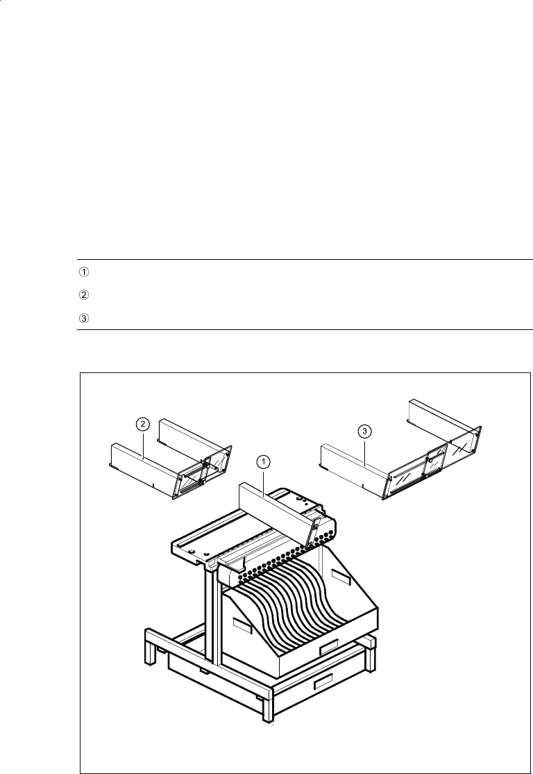
Description
The manual tray change is one
possibility for picking up Waffle
Packs. A number of “manual
trays” are placed on the compo-
nent tables (right-hand table for
Fine Pitch components). The two
component changeover tables are
retained.
This option is recommended if
only a few component types are
supplied in the tray.
JEDEC trays can be directly
clamped. Therefore there are spe-
cial access times for the place-
ment heads.
Component Supply:
Manual Trays
Technical Data
Sizes
136 x 360 mm; requires 5 feeder
locations
260 x 360 mm; requires 9 feeder
locations
Max. tray height 12.5 mm including component
Parts
Manual tray
Carrier tray
JEDEC Waffle Packs
Directly in the manual tray
136 mm wide
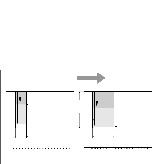
Pick & Place Head and Revolver Head Access to Manual Tray
Transport Direction
Revolver Head
Pick & Place Head
Feeder Table
Revolver Head
Pick & Place Head
Feeder Table
260
(136)
136
360
JEDEC Magazine Carrier Tray
119 mm
301 mm
157 mm
339 mm
19
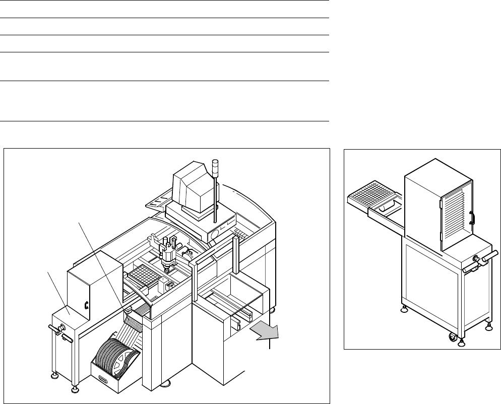
Description
If a number of Waffle Packs are
required during a placement proc-
ess, it is advisable to utilize the
automatic magazine change with
the help of the Waffle Pack
Changer. The set-up of the Waffle
Pack Changer is exactly coordi-
nated with the sequence of
placement for a work process op-
timized in terms of path and time.
An elevator automatically brings
the correct magazine into the
access range of the placement
head. The magazine for the first
component is changed as soon as
a PCB moves into the placement
conveyor and valid data for cluster
and set-up are available. The re-
maining magazine changes are
made in slack time during place-
ment. The magazines can be re-
plenished without any machine
idle time. The Pick & Place head
puts faulty components back
where it picked them up.
A narrow component table with 10
locations for feeder modules is
also available on the tray changer
(sample capacity: 20 tracks of
8 mm each).
Component Supply:
Waffle Pack Changer (Option)
Technical Data
Contents of storage 28 carrier trays for Waffle Packs
Max. magazine size 240 x 340 mm
Magazine height 15 mm including component
Max. number of
component types 200 per Waffle Pack Changer
Changing time
per magazine
< 3 s
parallel to other substeps during a
placement cycle
SIPLACE 80 F
4
with Waffle Pack Changer
Waffle Pack Changer
10 Feeder Positions
Waffle Pack
Changer
PCB Transport
Direction