SIPLACE 80 F4_EN.pdf - 第9页
8 Description R R R Re e e ev v v vo o o ol l l lv v v ve e e er r r r H H H He e e ea a a ad d d d A nozzle changer for the revolver head can be instal led to the left of the PCB conveyor w ith no loss of feeder locatio…
7
Description
The highly developed Pick & Place
or Fine Pitch placement head op-
erates on the Pick & Place princi-
ple. It is suitable for picking up par-
ticularly sophisticated or large
components as well as non-
standard models. High-resolution,
intelligent vision modules (Fine
Pitch and Flip Chip component vi-
sion modules) ensure that the
components are in satisfactory
condition that the placement posi-
tion is correct.
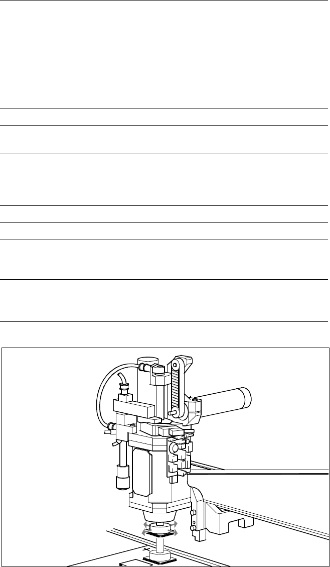
The sleeve with nozzle is the heart
of the Pick & Place head. The
sleeve is mounted such that it is
movable in the longitudinal (Z-axis)
and rotational direction (D-axis).
Each of the two axis are driven by
a DC motor; positioning is done by
incremental encoder. Thanks to a
high-resolution glass incremental
panel on the sleeve, the Pick &
Place head has an outstanding
high rotational position accuracy.
The rotating movement is trans-
mitted directly from D-axis motor
to the driving plate on the sleeve
via frictional wheel.
Placement Heads:
Pick & Place Head for High End / High Accuracy IC Placement
Technical Data
Component range
max. height
min. lead pitch
max. dimensions
max. weight
PCB-height ≤ 13.5 mm (20 mm* opti-
on) – thickness (PCB) – arching (PCB)
0.4 mm (standard), 0.25 mm (option)
32 x 32 mm (single measurement)
55 x 55 mm (multiple measurement)
25 g
Programmable placement force 1 to 10 N
Nozzles types
5 standard nozzles including
Flip Chip nozzle with nozzle changer
Component centering
Fine Pitch component vision module
(standard)
Flip Chip component vision module
(option)
Benchmark placement rate 1,800 cph
Resolution of the D-axis 0.005°
Angle accuracy
± 0.052° / 3 σ
± 0.07° / 4 σ
± 0.105° / 6 σ
Placement accuracy
± 37.5 µm/ 3 σ
± 50 µm/ 4 σ
± 75 µm/ 6 σ
* max. PCB-height is depending on the feeder (please contact Siemens service)
Pick & Place Head
PCB Transport
Direction
8
Description
R
RR
Re
ee
ev
vv
vo
oo
ol
ll
lv
vv
ve
ee
er
r r
r H
HH
He
ee
ea
aa
ad
dd
d
A nozzle changer for the revolver
head can be installed to the left of
the PCB conveyor with no loss of
feeder locations. It will change the
set-up of the placement head
quickly and reliably for the specific
nozzle configuration valid for a job.
Damaged or faulty nozzles can be
exchanged via the menu function.
P
PP
Pi
ii
ic
cc
ck
k k
k &
& &
& P
PP
Pl
ll
la
aa
ac
cc
ce
ee
e
H
HH
He
ee
ea
aa
ad
dd
d
SIPLACE 80 F
4
is equipped with a
nozzle changer for the Pick & Place
head. As standard, it is fitted with
one magazine. This can simultane-
ously hold 4 standard nozzles and
one special nozzle. The changer is
mounted on the right-hand side of
the PCB conveyor with no loss in
feeder locations. As an option, 3
additional nozzle magazines can be
installed for 5 nozzles each. Noz-
zles are exchanged automatically
during the placement sequence.
Placement Heads:
Nozzle Changer
Technical Data
12-Nozzle Revolver Head
Type of nozzle
All standard nozzles of nozzle series 6xx
and 7xx
(special nozzles must be tested individually)
Capacity
7 magazines for each 12 nozzles of one
nozzle series
Nozzle changing times About 2 s per nozzle
Pick & Place Head
Type of nozzle
All standard nozzles of nozzle series 4xx
(special nozzles must be tested individually)
Capacity
1 to 4 magazines each with 5 nozzles of
one nozzle series
Nozzle changing times About 2 s per nozzle
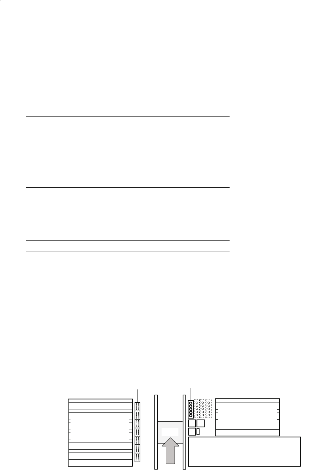
Position of Nozzle Changers
Waffle Pack Changer (Option)
Component Feeders
for Revolver Head /
Pick & Place Head
Component Feeders
for Revolver Head /
Pick & Place Head
PCB
Nozzle Changer for the
12-Nozzle Revolver Head Nozzle Changer Pick & Place Head for 5 Nozzles
Each with 7 Magazines for 12 Nozzles (Option) (Option: + 3 Nozzle Changers Each for 5 Nozzles

9
Description
Full Flip Chip handling capability on
the part of the SIPLACE 80 F
4
is
ensured by a flux dispenser in-
stalled directly next to the revolver
head. Immediately before the Pick
& Place head places the Flip Chip,
the mounting location on the PCB
is wetted with low-viscosity flux
by means of a dispensing needle.
The flux dispenser option essen-
tially comprises one stepping mo-
tor with piston, injector and valve
to change the operating mode (fill /
dispense injector) plus one storage
tank. The stepping motor positions
the piston over the storage tank to
be filled or over the Flip Chip
mounting location on the PCB for
emptying.
The purpose of a programmable
waiting time until PCB transport is
to allow the low-viscosity flux suf-
ficient time to dry so that the Flip
Chip(s) will not shift position while
the PCB is being moved out. A
new PCB conveyor control with
adjustable acceleration and delay
ramps makes programming the
waiting time largely superfluous.
Placement Heads:
Flux Dispenser for Full Flip Chip Capability (Option)
Technical Data
Programmable amount 2 µl to 100 µl
Smallest application incre-
ment
1 µl
Content of syringe 1 ml
Content of flux reservoir 100 ml
Volume to be applied at the
mounting location
Varies by Flip Chip size as well as wetting
properties of flux and substrate material
Flip Chip down holding time
after placement 0 to 5 s
Increment down holding ti-
me
0.01 s
Minimum waiting time prior
to PCB transport 0 to 40 s
Increment waiting time 1 s
Dispensing cycle time 1.5 s including positioning
Rinse cycle 1 to 10 x contents of syringe
Filling level 1 Warning
Filling level 2 Empty (causes machine stop)
Accuracy of dispenser
needle positioning
± 0.05 mm