SIPLACE 80 F4_EN.pdf - 第31页
30 Description Various fac tors contribute to the placement a ccuracy of the SIPLACE 80 F 4 machine, e.g ., the stationary PCB during the place- ment process. As no acceler ations are acting on the placed compo- nents, t…
29
Description
The optional coplanarity check fur-
ther enhances placement reliabil-
ity. This check is always con-
ducted right after the deviation of
position is ascertained with the
Fine Pitch vision module of the
Pick & Place head.
The coplanarity module is installed
next to the PCB conveyor along
with the Fine Pitch vision module
of the Pick & Place head.
One of the biggest problems in
Fine Pitch technology, the copla-
narity of leads, can be largely
eliminated by taking one additional
step during inspection. The copla-
narity module is employed to con-
duct a contactless, sequential ver-
tical scanning of the IC lead
structure on the basis of the laser
triangulation principle. The height
profile thus obtained for all of the
rows of leads is used to calculate
placement plane of the IC. The
programmed tolerance band based
on this placement plane then be-
comes effective.
If even one lead is outside this
placement area, the component is
excluded from the placement pro-
cess. It is gently placed back in the
Waffle Pack, entered on the repair
list and automatically repaired.
The component picked up by the
placement head may be crooked,
e.g., because one surface of the
package is not parallel to the row
of leads. The calculation of the
placement eliminates any influ-
ence this might have on
placement however.
As the result of extensive security
measures, the laser can only be
operated in the closed machine. It
then conforms to Safety Class 1
(not dangerous for eyes and skin).
Barring manipulation of the protec-
tive devices, the laser will not op-
erate outside the machine. Fol-
lowing impermissible tampering,
the laser complies with Class B.
On SIPLACE placement systems
the component which is picked up
is placed on the PCB immediately
after the coplanarity check. This
procedure ensures that no change
can occur after the check as the
result of any subsequent mechani-
cal influence. Unlike other designs,
with SIPLACE machines it is not
necessary to pick up the compo-
nent again or to transport it in a
special pick-up movement.
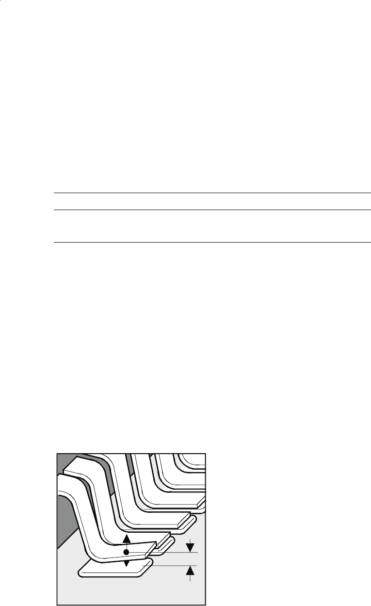
Vision Sensor Technology:
Coplanarity Module for the Pick & Place Head (Option)
Z
Effects of coplanarity (lateral ben-
ding of leads) of a populated com-
ponent
Accuracy of the coplanarity module
Uncertainty of checking in case of real components
Dimensions
U
99.73
[µm]*
32 x 32 mm
55 x 55 mm
21.5
22.7
* Checking uncertainty of a single measurement with a confidence interval of 99.73%
(corresponds to 3
σ
)
30
Description
Various factors contribute to the
placement accuracy of the
SIPLACE 80 F
4
machine, e.g., the
stationary PCB during the place-
ment process. As no accelerations
are acting on the placed compo-
nents, their position continues un-
changed. The PCB moves in and
out at a coordinated speed which
is automatically reduced just be-
fore the nominal position is
reached.
A further guarantee for long-term
high placement accuracy is the
position recognition of the axes of
the gantry and placement head by
means of optical scanning by in-
cremental encoders. Revolving
star and segments of the revolver
head are positioned by means of
high-resolution glass incremental
panels. The X- and Y-axes are posi-
tioned with the help of the metal
scales on each gantry axis.
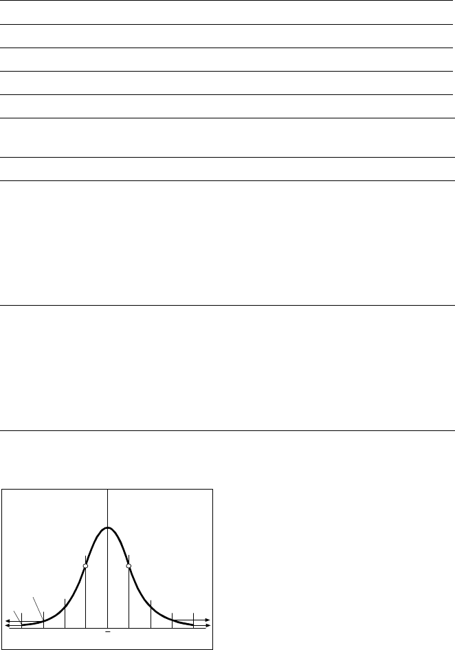
To determine the placement accu-
racy on SIPLACE machines, highly
precision glass components with
mounted structures are placed on
a dimensionally accurate glass
mapping plate. The results are sta-
tistically evaluated and presented
as a Gaussian standard distribu-
tion. In the case of the 12-nozzle
revolver head the placement accu-
racy is ± 90 µm at a statistical reli-
ability of 4 sigma. In other words,
of one million placed components,
60 are outside the specified toler-
ance (= 60 dpm). If the accuracy
value ± 90 µm is divided by the
sigma value 4, the result is the
standard deviation S of 1 sigma =
± 22.5 µm.
A machine capability analysis is
conducted for each machine ac-
ceptance test.
Machine Criteria:
Placement Accuracy
Technical Data Gantry
Drive DC servomotors
Position measuring system (X/Y) Linear scales
Resolution of X-/Y-axis 2.5 µm
Speed of X-axis max. 2 m/s
Speed of Y-axis max. 2.5 m/s
Accuracy
X-/Y- and D-axis offset in optical component and PCB centering
12-nozzle revolverhead
Angle accuracy
Placement accuracy
± 0.525° / 3 σ
± 0.70° / 4 σ
± 1.05° / 6 σ
± 67.5 µm/ 3 σ
± 90 µm/ 4 σ
± 135 µm/ 6 σ
Pick & Place-head
Angle accuracy
Placement accuracy
± 0.052° / 3 σ
± 0.07° / 4 σ
± 0.105° / 6 σ
± 37.5 µm/ 3 σ
± 50 µm/ 4 σ
±75 µm/ 6 σ
Standard Deviation - dpm
-4
σ
-3
σ
-2
σσ
x
σ
2
σ
3
σ
4
σ
2700 dpm
60 dpm
P Point of Inflection
31
Description
P
PP
Pl
ll
la
aa
ac
cc
ce
ee
em
mm
me
ee
en
nn
nt
t t
t R
RR
Re
ee
eli
lili
lia
aa
ab
bb
bili
iliili
ilit
tt
ty
yy
y
Aside from correct positioning,
placement reliability also means a
gentle handling of the compo-
nents, so that these can be sol-
dered well later. Rework is mini-
mized or eliminated as a result.
On the SIPLACE 80 F
4
among
others this is ensured through a
number of control functions, e.g.,
the vacuum checks and compo-
nent vision test during the revolver
head sequence.
Unsuitable components are re-
jected, placed on the repair list and
automatically processed during a
repair cycle. An offset in the posi-
tion of the PCB relative to the con-
veyor system (PCB vision) and an
offset of the X-axis, Y-axis or rota-
tion of the component relative to
the midpoint of the nozzle (com-
ponent vision) trigger an immedi-
ate correction and thus placement
accuracy.
Thanks to the motionless PCB the
components remain in the exact
position they were placed. The
stationary component table pro-
tects, for example, the compo-
nents in Bulk Cases against dam-
age such as may occur due to
vibrations which are inevitable with
other placement concepts. Op-
tional add-on products ensure fur-
ther reliability: With the aid of the
component bar code scanner, the
correct placement program is
automatically sent to the station.
P
PP
Pi
ii
ic
cc
ck
kk
k-
--
-u
uu
up
p p
p e
ee
er
rr
rr
rr
ro
oo
or
rr
rs
ss
s
All errors which occur between the
time the component is picked up
and the time it is placed on the
PCB are pick-up errors. They in-
clude:
No component in the tape
Component cannot be removed
from the tape.
Vacuum error
Vision error due to faulty com-
ponent
Vision error due to unrecognized
component
P
PP
Pl
ll
la
aa
ac
cc
ce
ee
em
mm
me
ee
en
nn
nt
t t
t e
ee
er
rr
rr
rr
ro
oo
or
rr
rs
ss
s
Errors which occur after the com-
ponent has been placed on the
PCB. They include:
Rotation error
Too many components on PCB
X/Y-offset
P
PP
Pl
ll
la
aa
ac
cc
ce
ee
em
mm
me
ee
en
nn
nt
t t
t S
SS
Sp
pp
pe
ee
ee
ee
ed
dd
d
When used alone on the SIPLACE
80 F
4
the 12-nozzle revolver head
achieves a benchmark placement
rate of 10,000 components per
hour (cph). The Pick & Place head
places at a max. speed of 1,800
cph. These benchmark rates can
be verified on the demonstration
PCB at Siemens.
Factors such as PCB size, number
of components per board and their
layout have a certain effect on the
speed in actual practice. The
placement speed in practice can
be predicted using a calculation
program.
Machine Criteria:
Placement Reliability and Placement Speed
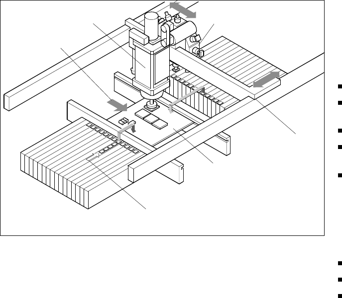
Placement Principle SIPLACE 80 F
4
Pick & Place Head
PCB Transport
Direction
Revolver Head
X/Y-Gantry
System
Fixed PCB
Fixed Component
Su
pp
l
y