SIPLACE 80 F4_EN.pdf - 第5页
4 Input S tation Screen Printer Oven SIPLACE 80 S-20 SIPLACE 80 S-20 SIPLACE 80 F 4 with Waffle Pack Changer Output Station Example of a S IPLACE P lacement Line Description The modular SIPLACE des ign is charac terized …

3
Description
The SMD General Purpose Placer
SIPLACE 80 F
4
has four outstand-
ing features: Flexibility, Fine Pitch
processing, Flip Chip processing
and Fast-placement. This place-
ment system combines the Fine
Pitch Pick & Place head with the
12-nozzle revolver head (Collect &
Place) to unite high precision with
high speed.
Equipped with the 12-nozzle re-
volver head the SIPLACE 80 F
4
placement system optimally com-
plements, the SIPLACE 80 S-20
machine. It eases the burden of
high-speed chip placement and
ensures an outstanding product
throughput time. While the PCB is
still being moved, the 12-nozzle
revolver head is already picking up
the first components. As soon as
the PCB is clamped in the con-
veyor, its exact position is deter-
mined with the PCB camera. Af-
terwards the revolver head picks
up the remaining components for
the entire rotation step and places
its 12 components. As soon as it is
finished, the Pick & Place head
begins picking up and placing the
components assigned to it.
The principle of the stationary PCB
and the motionless component ta-
ble has decisive advantages:
Component tapes of all sizes
can be spliced, preventing ma-
chine stoppage due to empty
feeders.
The feeding of components
with no vibrating enables a reli-
able pick-up of even the small-
est components (e.g., 0402
chips).
Thanks to the flexible 12-nozzle
revolver heads - whose ideal
nozzle set-up is automatically
specified - the travel can be
minimized and the sequence of
placement optimally adjusted.
Holding the PCB stationary pre-
vents components from shifting
during placement.
Speed coupled with economic ef-
ficiency and set-up reliability is the
SIPLACE 80 F
4
recipe for success.
The product range is rounded off
by optional additional products
such as component changeover
tables, tray changers, component
and PCB bar code scanners or
automatic nozzle changer.
Machine Description
Technical Data
Process Pick & Place / Collect & Place
Range of components 0402 to 55 x 55 mm
Benchmark placement rate
12-nozzle revolver head
Pick & Place head
10,000 cph
1,800 cph
12-nozzle-revolver head
Angle accuracy
Placement accuracy
± 0.525° / 3 σ, 0.70° / 4 σ, 1.05° / 6 σ
± 67.5 µm/ 3 σ, 90 µm/ 4 σ, 135 µm/ 6 σ
Pick & Place head
Angle accuracy
Placement accuracy
± 0.052° / 3 σ, 0.07° / 4 σ, 0.105° / 6 σ
± 37.5 µm/ 3 σ, 50 µm/ 4 σ, 75 µm/ 6 σ
PCB dimensions
50 x 50 mm to 460 x 460 mm
(optional 460 x 508 mm)
Feeder capacity 40 feeder locations
Component table
Types of Feeder modules
Changeover table, Waffle Pack Changer,
manual trays
Tapes, stick magazines, Bulk Cases
Operating system Microsoft Windows / RMOS
Connection In line or stand alone
Space required 4 m² / module

4
Input Station
Screen Printer
Oven
SIPLACE 80 S-20
SIPLACE 80 S-20
SIPLACE 80 F
4
with Waffle Pack Changer
Output
Station
Example of a SIPLACE Placement Line
Description
The modular SIPLACE design is
characterized by flexibility and
adaptability. It permits an individual
production line composition of
similar and different modules.
When performance requirements
change the individual machines
can be recombined quickly and
without complications, one of the
major reasons being their relatively
small size.
The SIPLACE family offers the
right product for each purpose -
from high-speed SMD placement
systems SIPLACE 80 S-20 to the
flexible Fine-Pitch placement
system SIPLACE 80 F
4
.
SIPLACE 80 F
4
is ideally suited for
fixed set-up as well as for family
set-up with optimized changeover
times. When the required capacity
is low, however, it is also suitable
as a standalone placement sys-
tem.
Line Design
Technical Data
System SIPLACE SMD placement lines
Modules
SIPLACE 80 S-20 / SIPLACE 80 F
4
/
SIPLACE HS-50 / SIPLACE S-23 HM /
SIPLACE F
5
Peripherals
Input/output station, screen printer,
solder oven, inspection conveyor etc.,
available from Siemens
Component range 0201* to 55 x 55 mm**
PCB conveyor
PCB dimensions
Ceramic substrate dimensions
Automatic width adjustment
50 x 50 mm to 460 x 460 mm
(optional 460 x 508 mm)
2" x 2" to 4" x 7"
Placement speed depends on layout of modules
Space required
4 m² / SIPLACE S & F modules
7.5 m² / SIPLACE HS module
* Collect & Place
** Pick & Place
5
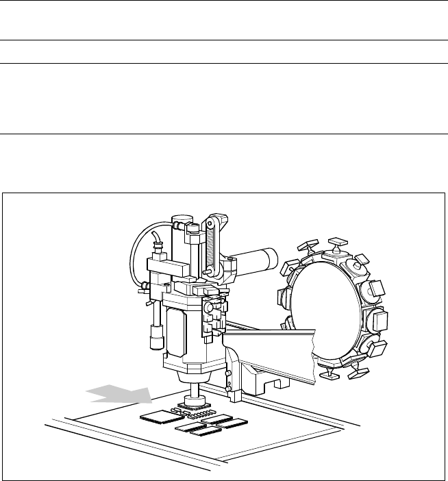
Description
The main X-/Y-gantry features two
placement heads, the 12-nozzle
high-speed revolver placement
head and the high-precision Pick &
Place head or Fine Pitch place-
ment head.
With certain overlapping, each
placement head is specialized for a
specific range of components.
Therefore it is possible to option-
ally distribute the components to
be placed between the two heads.
Placement Heads
Technical Data
Placement principle
Pick & Place (Pick & Place head)
Collect & Place (Revolver head)
Components Entire SMD range
Component table:
Pick & Place head
12-nozzle revolver head
Feeder on changeover table
Waffle Pack Changer or manual trays
Feeder on changeover table
Placement Heads SIPLACE 80 F
4
Pick & Place Head
Collect & Place
Revolver Head
PCB Transport
Direction