Siplace TX-设备参数-EN.pdf - 第22页
22 Component feeding Alternative SIPLACE feeder modules JTF-ML 2 The SIPLACE TX can accommodate a SIPLACE JTF-ML 2 at locat ion 1. The SIPLACE JTF-ML 2 is fitted to the side. Depending on the magazine type, the SIPLACE J…
21
Component feeding
Alternative SIPLACE modules
SIPLACE Glue Feeder
The SIPLACE Glue Feeder
allows you to position dots of
adhesive on a component,
before it is placed. These
dots of adhesive can then be
checked by the SIPLACE
Vision system. The required
glue dots can be defined in
the Component Shape
Editor in SIPLACE Pro and
you can also define whether
individual dots of adhesive
are to be excluded from
inspection or not.
This adhesive function can
be enabled and disabled in
the Component Editor in
SIPLACE Pro. The SIPLACE
Glue Feeder is a special
feeder module which needs
to be manually configured as
a fixed feature on a certain
table track.
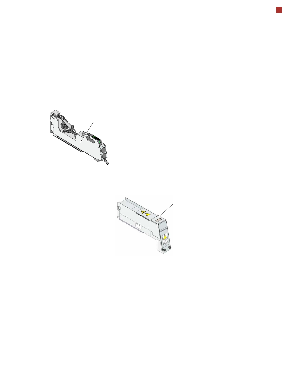
Linear Dipping Unit X
(LDU X)
The LDU X is used for coat-
ing Flip-Chips and CSP com-
ponents with fluxThe flux
container slides with a linear
movement over the dip plate
and coats the cavity in the dip
plate with a layer of flux (pre-
defined layer thickness). The
parameters for coating a
component with flux are pre-
scribed in SIPLACE Pro. The
component is coated and
then the flux layer is
renewed.
This sequence guarantees
consistent processing condi-
tions for the components.
The LDU X is taken into
account as an independent
feeder module type in the
setup. This module can be
set up on the component trol-
leys of the SIPLACE TX-
Series. An implemented
warming function allows the
viscosity of the flux to be
altered.
Linear Dipping Unit (occupies 5 loca-
tions of an 8 mm X feeder module
SIPLACE Glue Feeder (occupies 9 locations of an
8 mm X feeder module, max. 1 per head)
22
Component feeding
Alternative SIPLACE feeder modules
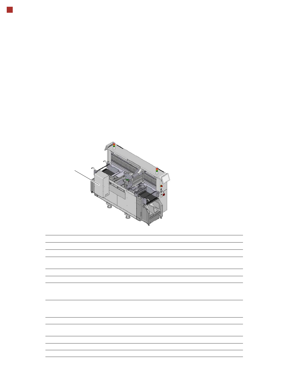
JTF-ML 2
The SIPLACE TX can
accommodate a SIPLACE
JTF-ML 2 at location 1. The
SIPLACE JTF-ML 2 is fitted
to the side.
Depending on the magazine
type, the SIPLACE JTF-ML
2 stores up to 18 thin or, as
an option, 14 thick JEDEC
waffle pack trays in an
exchangeable cassette and
supplies them as required.
The placement machine can
therefore be supplied with
different component types at
variable changeover times.
An output conveyor
extension is required when
using the JTF-ML 2. This
extends the conveyor by
600 mm.
Technical data
Width x length x height (tower)
374.5 mm x 322.7 mm x 707.0 mm
Width x length x height (conveyor)
356.2 mm x 346.0 mm x 68.2 mm
Weight
Tower (empty): 26.3 kg (58.0 lbs.)
Total: ~36 kg (79.4 lbs.) (depending on application)
Storage capacity
JEDEC waffle pack tray specification JEDEC Standard: 95-1 & IEC 60286-5
Waffle pack tray, thin 18 JEDEC waffle pack trays or
18 magazine trays (cookie trays)
(in two cassettes)
Thick waffle pack tray 14 JEDEC waffle pack trays or
14 magazine trays (cookie trays)
(in two cassettes)
Waffle pack tray changeover time 3.15 to 6.1 seconds (depending on application
a
)
a) 3.15 seconds to the next waffle pack tray with maximum acceleration, 6.1 seconds from the first to the
ninth waffle pack tray with minimum acceleration
Slot n to n+1 3.15 to 5.4 seconds (maximum/minimum accelera-
tion)
Cassette
Width x length x height 343.7 mm x 136 mm x 137 mm
Max. load weight (per cassette 4.45 kg (incl. weight of cassette)
JTF ML 2

23
SIPLACE Vision
High Placement Performance and Best Quality
SIPLACE Vision is designed
to recognize and measure
components and boards
(substrates), so that these
can then be placed and con-
nected precisely.
In the placement area,
SIPLACE Vision determines
the position of the compo-
nent on the nozzle and there-
fore facilitates exact
positioning of components
on the printed circuit boards.
There is a large component
library available which
already contains all standard
component shapes. Wizard
assistants, such as the Com-
ponent Shape Wizard, make
it easier to create new com-
ponent shapes.
Component recognition
SIPLACE Vision identifies each individual component by its geometry and color. Even complex com-
ponent shapes are detected with high reliability. This component recognition check is performed in a
single step, with no extra time involved but with optimum scanning of each individual component. The
camera types are adjusted to the various head types and present a range of different resolutions, field
of vision sizes, illumination types and focal areas. See also the technical data for the relevant place-
ment heads from page 9 onwards. With the help of different illumination levels and brightness stages,
almost every component shape can be easily recognized. The system also saves images of the com-
ponents, so-called "Vision dumps". These enable you to analyze rejected components and to further
improve component shape descriptions. This supports the early recognition of faults in new products
and increases process reliability. These vision dumps also serve as evidence in the event of defective
component supplies.
Component recognition is used for:
• Tolerance checks for component dimensions, L x W, (shape)
• Tolerance checks for component features e.g.:
• Lead/ball grids
• Lead/ball length/diameter
• Deformed leads/missing balls
• Damage/discoloration
• Flipped/face down
• Vision dumps in the event of malfunctions
• Pin 1 / polarity recognition
• Pattern matching
• Glue dot inspection
• Reading component barcodes/data matrix codes
• Pickup reliability
• Pocket measurement
• Tray measurement
• Offset of component to nozzle center and dynamic correction of pickup position