Siplace TX-设备参数-EN.pdf - 第8页
8 SIPLACE placement heads General Head modularity The SIPLACE placement machines are dis tinguished by maximum flexibility in the production pr ocess. This flexibility is in part due to the head modu larity of the plac e…

7
Machine performance
Placement head types SIPLACE SpeedStar (C&P20 P)
SIPLACE MultiStar (CPP)
SIPLACE TwinStar (TH)
Placement performance
The placement performance is influenced by the different head combinations and head positions, plus the con-
veyor configurations. Individual options and customized applications also influence the placement performance.
On request, ASM can calculate the actual performance of your product on your machine configuration.
IPC value [components/h]
Conducted with 0201 components, in accordance with the layout of the IPC 9850 standard of Association Con-
necting Electronics Industries.
SIPLACE benchmark value [components/h]
The SIPLACE benchmark value is measured during the machine acceptance tests. It corresponds to the condi-
tions set out in the ASM scope of service and supply.
Theoretical maximum output value [components/h]
The theoretical maximum output value is calculated from the most favorable conditions for each machine type
and setting, and corresponds to the theoretical conditions normally used in the industry.
SIPLACE TX2i placement
machine
Placement area IPC value Benchmark value Theoretical value
C&P20 P / C&P20 P 67,000 78,000 103,800
CPP_L / C&P20 P 55,000 63,000 83,455
CPP_L/CPP_L 43,600 48,000 63,900
CPP_H / CPP_H 41,000 45,000 59,850
SIPLACE TX2 placement
machine
Placement area IPC value Benchmark value Theoretical value
C&P20 P / C&P20 P 65,000 75,500 100,500
CPP_L/CPP_L 42,600 46,500 61,900
CPP_H / CPP_H 40,000 44,000 52,500
TH / CPP_H 25,000 28,500 38,000
SIPLACE TX1 placement
machine
Placement area IPC value Benchmark value Theoretical value
C&P20 P 32,500 37,500 50,200
CPP_H 20,000 22,000 26,250
TH 5,050 5,500 7,300
CPP_H = Multistar CPP in high assembly position
CPP_L = Multistar CPP in low assembly position
8
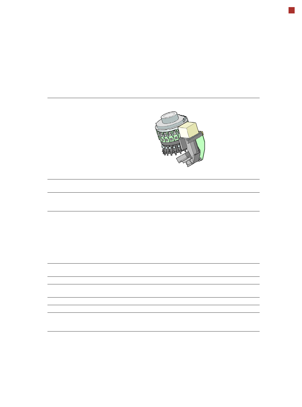
SIPLACE placement heads
General
Head modularity
The SIPLACE placement
machines are distinguished
by maximum flexibility in the
production process. This
flexibility is in part due to the
head modularity of the place-
ment machines, which allows
different placement head
variants to be configured to
suit the production require-
ments.
The SIPLACE SpeedStar
and the SIPLACE MultiStar
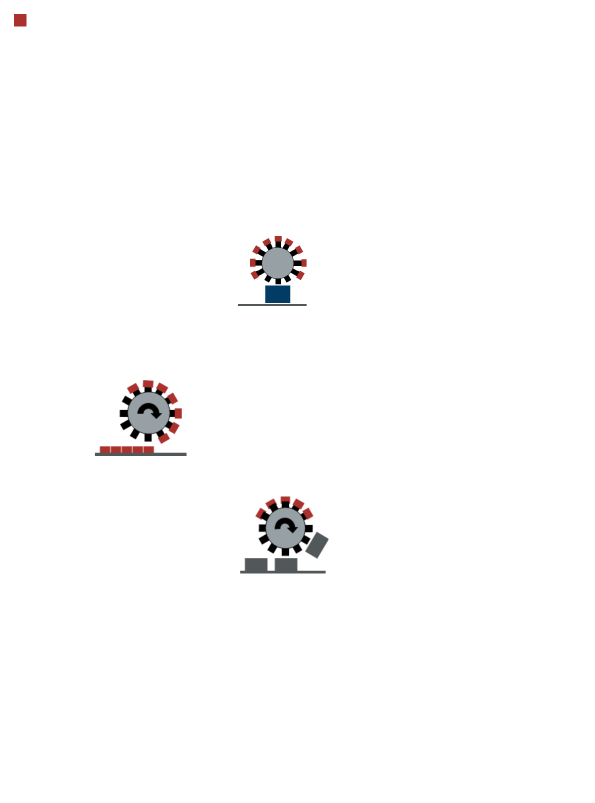
operate according to the
Collect&Place principle i.e.
one cycle includes pickup or
"collection" of 20 or 12 com-
ponents, their optical center-
ing on the board and their
rotation into the required
placement angle and posi-
tion. They are then placed
gently and accurately onto
the PCB. This principle is
particularly suitable for high-
speed placement of standard
components.
The SIPLACE MultiStar also
functions according to the
Pick&Place principle. Two
components are picked up
by the SIPLACE MultiStar,
optically centered on the way
to the placement position
and rotated into the required
placement angle. This princi-
ple is particularly suitable for
fast and precise placement
of large components.
The SIPLACE MultiStar uses
both the Collect&Place and
the Pick&Place principle.
Mixed Mode allows com-
bined use of these two
modes, which were previ-
ously separated from one
another, in one placement
cycle.
Pick&Place mode (Twin
Head)
The high-precision SIPLACE
TwinStar functions according
to the Pick&Place principle.
Two components are picked
up by the SIPLACE Twin-
Star, optically centered on
the way to the placement
position and rotated into the
required placement angle.
This principle is particularly
suitable for fast and precise
placement of special compo-
nents, such as those
required for grippers etc..
Control and self-learning
functions
The reliability of the
SIPLACE placement heads
can be enhanced even fur-
ther with various checking
and self-learning functions.
• Component sensor
Checks the presence of
the components on the
nozzle before the pickup
and placement process
• Digital camera
Checks the position of
each component on the
nozzle. This check is per-
formed in a single step,
with no extra time involved
but with optimum scan-
ning of each individual
component.
• Force sensor
Monitors the prescribed
component set-down
force.
The sensor stop proce-
dure enables compensa-
tion of height differences
during pickup and PCB
warpage during place-
ment.
• Vacuum sensor
Checks whether the com-
ponent was correctly
picked up or placed.
Collect&Place mode
Pick&Place mode
(SIPLACE MultiStar)
Mixed mode
9
Placement heads
SIPLACE SpeedStar (C&P20 P)
SIPLACE SpeedStar (C&P20 P)
With component camera
type 23
With component camera
type 41
Component range
a
a) Please note that the placeable component range is also affected by the pad geometry, the customer-spe-
cific standards, the component packaging tolerances and the component tolerances.
01005 to 2220, Melf, SOT,
SOD
0201 (metric) to 2220, Melf,
SOT, SOD, Bare-Die, Flip-
Chip
Component spec.
Max. height
Min. lead pitch
Min. lead width
Min. ball pitch
Min. ball diameter
Min. dimensions
Max. dimensions
Max. weight
4 mm
0.25 mm
0.1 mm
0.4 mm
0.2 mm
0.18 mm x 0.18 mm
6 mm x 6 mm
1 g
4 mm
0.08 mm
0.03 mm
0.10 mm
0.05 mm
0.12 mm x 0.12 mm
6 mm x 6 mm
1 g
Programmable set-down
force
1.3 - 4.5 N 1.3 - 4.5 N
Nozzle types 40xx 40xx
X/Y accuracy
b
b) The accuracy values are measured during the machine acceptance tests. They correspond to the condi-
tions set out in the ASM scope of service and supply.
± 30µm / 3σ ± 30 µm/3σ
± 25 µm / 3σ with HPF
c
c) HPF = High Precision Flag
Angular accuracy ± 0.5° / 3σ ± 0.5° / 3σ
Illumination level 5 5
Standard functions High-resolution camera, vacuum sensor, force measurement, component
sensor, integrated turning station per segment, PCB warpage check, individ-
ual image of each component