Siplace TX-设备参数-EN.pdf - 第30页
30 SIPLACE Vision Barcode and data matrix code 1D Barcodes 1D Barcodes Code types Code 39 Code 93 Code 128 EAN-8 (AddOn 2, AddOn 5), EAN-13 (AddOn 2, AddOn 5) Interleaved 2 of 5 (station software version 710.1 or higher …

29
SIPLACE Vision
Barcode and Data Matrix Codes
Description and technical data
Description
The PCB camera can read
either a barcode or a data
matrix code. The data can be
used for traceability pur-
poses.
The barcode can be on the
board itself or on a compo-
nent. In addition, it is also
possible to attach a barcode
label to a board or a compo-
nent and to then read this
barcode label with the PCB
camera, directly after place-
ment. The focal height must
be taken into account during
reading, if there is a barcode
or barcode label on the top of
a component.
Data Matrix Codes
Code types supported Only Data Matrix ECC 200 is supported.
No. rows/columns All combinations of rows/columns as defined in the standard will be
accepted, including rectangular symbols and large symbols with multi-
ple data areas.
Minimum dot size 50 µ
Maximum size of data matrix
codes
X
≤ 30 mm and Y ≤ 30 mm, or
X ≤ 10 mm and Y ≤ 100 mm, or
X
≤ 100 mm and Y ≤ 10 mm
Symbol angle All symbol angles will be accepted.
Inverse symbols Inverse symbols (light modules on a dark background) will be
accepted.
Mirrored symbols Mirrored symbols will be accepted.
(Station software version 707.1 SP2 or higher required)
Ratio of column width to row
height
1/2
≤ (column width) / (row height) ≤ 2
Region of Interest (ROI) The area in which the barcode is searched for (ROI) should not
exceed the following values:
Width of ROI
≤ 6 * width of barcode symbol
Height of ROI
≤ 6 * Height of barcode symbol
Contrast Minimum 20 gray values.
Print growth The size of a module must be at least 1/3 of the cell size in the data
matrix grid.
The size of a module must be at most 5/3 of the cell size in the data
matrix grid.

30
SIPLACE Vision
Barcode and data matrix code
1D Barcodes
1D Barcodes
Code types Code 39
Code 93
Code 128
EAN-8 (AddOn 2, AddOn 5), EAN-13 (AddOn 2, AddOn 5)
Interleaved 2 of 5 (station software version 710.1 or higher required)
Minimum width of bar 50 µ
If the quality of the marking is high enough, the width can be reduced
down to 30 µ.
Maximum size of barcode X
≤ 30 mm and Y ≤ 30 mm, or
X ≤ 10 mm and Y ≤ 100 mm, or
X ≤ 100 mm and Y ≤ 10 mm
Minimum height of symbol 5% of length of whole symbol.
Symbol angle All symbol angles will be accepted.
Inverse symbols Light bars on a dark background will be accepted.
(Station software version 708.0 or higher required)
Mirrored symbols Mirrored symbols will be accepted.
(this corresponds to a rotation of 180 degrees for 1D codes)
Region of Interest (ROI) The area on the board, in which the barcode is searched for (ROI),
should not exceed the following values:
ROI (direction of reading)
≤ 3 * symbol width
ROI (vertical to direction of reading)
≤ 10 * symbol width
Uniformity of bars and spaces Each bar and space represents 1 to 4 bits (applies to all code types
implemented), whereby the number of bits corresponds to the width of
the bar/space. When the barcode is read with the PCB camera, it is
assumed that the code is flat. This is why the same nominal width is
applied to all bars and spaces in the symbol when reading 1D bar-
codes with the PCB camera. As a consequence, barcodes cannot be
read if a bar/space with n bits appears to be smaller than another bar/
space with n-1 bits.
31
SIPLACE Vision
Options
OSC package
The licensed OSC package
contains functions for simpli-
fied placement of odd
shaped components (OSC),
such as connectors or sock-
ets.
The license is activated via
SIPLACE Pro.
The following functions are
contained in the OSC pack-
age:
OSC measurement options
• Customized odd shaped
component
This enables the user to
describe any abstract pat-
tern on a component e.g.
connection leads of a tri-
angular shape. This pat-
tern can then be easily
created and edited at the
station, using the wizard
function.
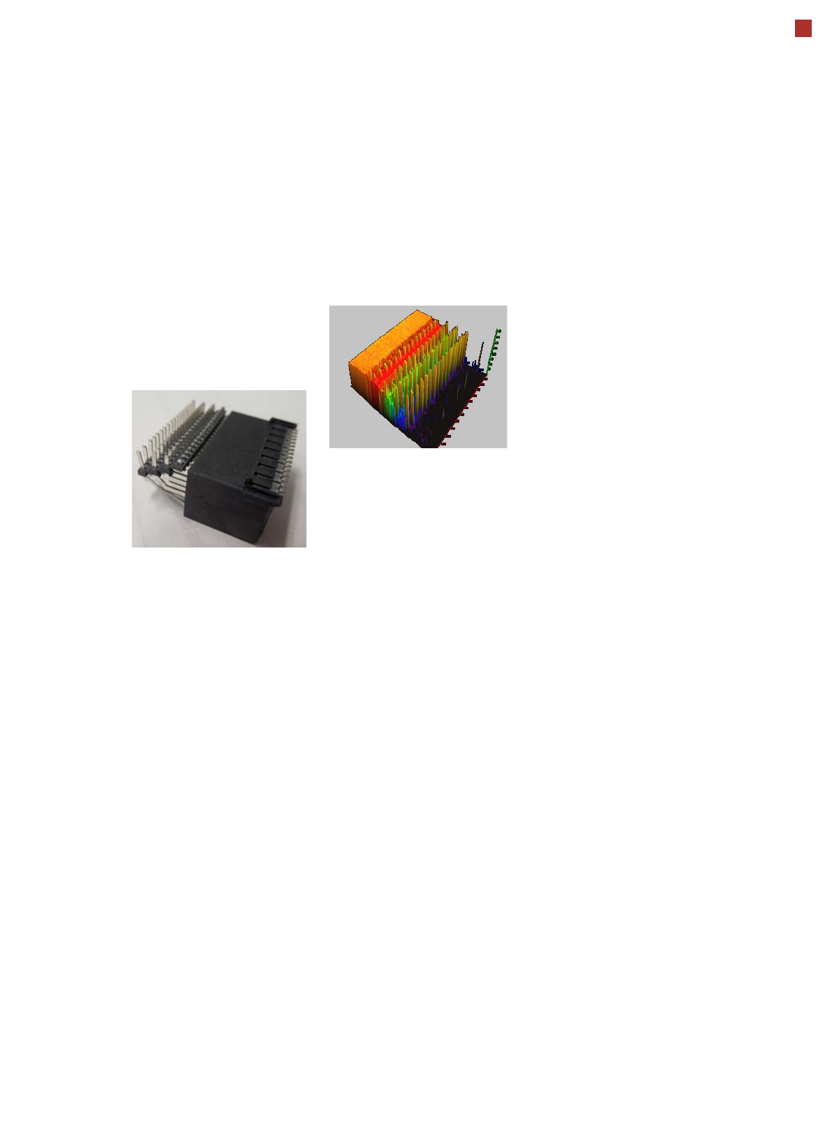
• Stereo measurement
Stereo measurement
means that two images
are taken of each compo-
nent, from different direc-
tions, using a stationary
camera. These images
are overlapped to show
connectors, pins etc. in 3D
to support easy and pre-
cise evaluation of struc-
tures which, due to color,
shading or background
structures, are difficult to
recognize in conventional
2D measurement.
• Special position evalua-
tion
This function supports
separate definition of posi-
tion determining features
(x,y, angle) independent
of the features for good-
bad recognition. Place-
ment of snap-in compo-
nents
This function monitors
whether snap-in components
engage in the board prop-
erly, during automatic place-
ment.
Automatic calculation of
optimum acceleration
This function enables the
user to automatically calcu-
late the optimum accelera-
tion of individual axes for a
component at the station.
The acceleration values
found can then be checked in
an additional test run and
sent back to the program-
ming system if successful.