00196378-0102_UM X-Feeder_EN.pdf - 第22页
Overview of X Feeder Modules Functions and Operating Contr ols Display at the Tape Feeder Modules 22 User Manual X Feeder Modules SIPLACE Family 3.1.2 Display at the Tape Feeder Modules 3.1.2.1 LED Display on the 2x8 mm …
Overview of X Feeder Modules
Structure of the SIPLACE X-Series Tape Feeder Modules Functions and Operating Controls
User Manual X Feeder Modules SIPLACE Family 21
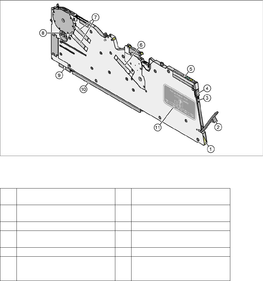
8 mm X tape feeder module - rear view
Legend
(1) Entry to the empty tape duct with tape
spring
(2) Removal flap to the foil container
(3) Integrated blade for cutting off the
cover foil
(4) Removal handle, engaged
(5) Operator panel (6) Drive motor for foil removal
(7) Drive motors for the tape conveyor (8) Rotary valve for removing compo-
nents
(9) Front sliding guide (10) Rear sliding guide
(11) Graphical representation of the pick-
up position in relation to the compo-
nent size
Overview of X Feeder Modules
Functions and Operating Controls Display at the Tape Feeder Modules
22 User Manual X Feeder Modules SIPLACE Family
3.1.2 Display at the Tape Feeder Modules
3.1.2.1 LED Display on the 2x8 mm Tape Feeder Modules
Status display
▪ If the status display lights up green, the respective track of the feeder module is ready-to-operate
and needed for the current placement job. This status display also lights up green, if no placement
job has been assigned yet.
▪ If the status display is orange, this indicates that a warning has been issued.
▪ If the status display lights up red, an error has occurred. In the case, the pitch display indicates the
error source.
▪ If the status display remains dark, the feeder module is not needed for the current placement job.
Definitions of Terms Describing the Operating and Display Functions
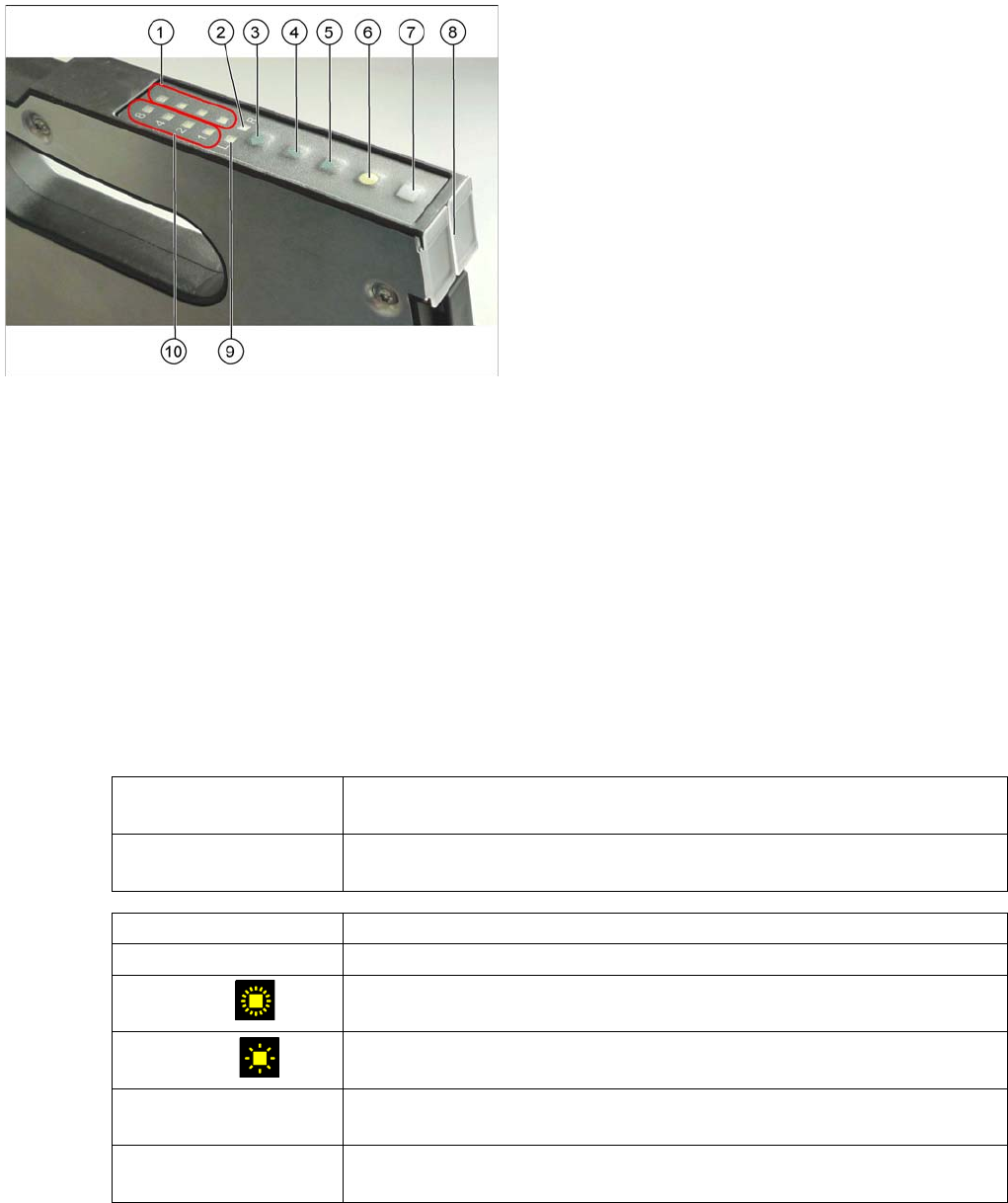
Operator panel of the 2x8 mm tape feeder modules
Legend
1. Pitch display (LEDs) right
2. Track display right
3. Track change button
4. Forwards button
5. Backwards button
6. Foil button
7. Set button
8. Status display (2x)
9. Track display left
10. Pitch display (LEDs) left
The X feeder modules are equipped with 10 LEDs
(1, 2, 9 and 10) for indicating the operating states and
one multi-colored status display for each track (8).
Display The display indicates a specific status (e. g. the currently set pitch or the se-
lected track) and consists of several LEDs.
LED Abbreviation for "light emitting diode". LED designates a single element in a
display (e. g. left track "L").
Short press of the button The button is pressed and released within 0.75 seconds.
Long press of the button The button is being pressed more than 0.75 seconds.
Fast flashing
The LED is on and off for 0.15 second each, i. e., it flashes 3.3 times per
second.
Slow flashing
The LED is on and off for 0.45 second each, i. e., it flashes approx. once per
second.
Running light forwards The LEDs 1, 2, 4 and 8 of the pitch display light up one after another and
then they are all off. After that this sequence is repeated.
Running light backwards The LEDs 8, 4, 2 and 1 of the pitch display light up one after another and
then they are all off. After that this sequence is repeated.

Overview of X Feeder Modules
Display at the Tape Feeder Modules Functions and Operating Controls
User Manual X Feeder Modules SIPLACE Family 23
Ad 1.: Pitch display
The currently set pitch is indicated at the operator panel for both tracks by the corresponding LED 1, 2,
4 or 8.
Ad 2.: Track display
Indicates the relevant active track, that is triggered by the operating buttons. There is a left (L) and a
right (R) track.
Ad 3.: TRACK CHANGE button
Short press: When the TRACK CHANGE button is released, the track display switches to the
other track. The following button inputs will trigger this track until the TRACK
CHANGE button will be pressed again.
The 2x8 mm X feeder module consists of two individual 8 mm tracks. Both tracks
are controlled via the operator panel, although only one track can be active at any
one time. The other buttons, FORWARDS; BACKWARDS; FOIL and SET, always refer
to the currently active track.
Ad 4.: FORWARDS button
Short press: When the button is released, a tape transport cycle in forward direction is started
using the currently set pitch.
Long press: a) The foil is not tensioned: The tape drive continuously transports forwards as
long as the button remains pressed.
b) The foil is tensioned: The tape is repeatedly transported forwards as long
as the button remains pressed.
Ad 5.: BACKWARDS button
Short press: When the button is released, a tape transport cycle in backward direction is started
using the currently set pitch.
Long press: a) The foil is not tensioned: The tape drive continuously transports backwards as
long as the button remains pressed and the foil rocker
does not move down.
b) The foil is tensioned: The tear down procedure is enabled.
c) Torn foil error active: The tear down procedure is performed immediately.
Caution: If you pace the feeder module backwards, lift the pickup window from the cover foil by pushing
it up or by using the locking latch. Otherwise, the cover foil will be damaged.
Ad 6.: FOIL button
By pressing this button the foil removal motor is started.
It is moving until one of the following events occurs:
▪ the button was released
▪ the button was pressed longer than 30 sec. and the foil is not tensioned yet
The foil tension made the rocker move down to the switch off point.
Ad 7.: SET button
Together with the FORWARDS, BACKWARDS or FOIL button the SET button serves for setting the
pitch and the pickup position.
Ad 8.: STATUS display
Indicates the current status of both tracks.