manual-gsf-guide-kit-0028099_ID-220219_EN.pdf - 第6页
325 º C 24.0 mm/ s 25% 75% Po w e r Con �nuous 50% 19:29 Sel. t emp. 325 º C Ø 1.00 mm Suppli e d: 12 mm Lan gu ag e T oo l se �n gs Coun t er s R ese t Exit F eeder se �n gs 325 º C 24.0 mm/ s 25% 75%…
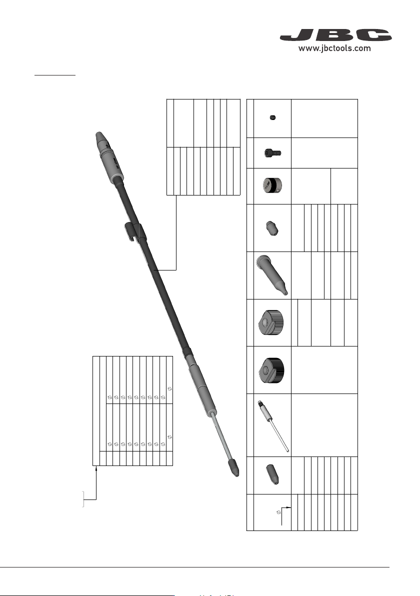
GSFXXD-B
WITHOUT SOLDER WIRE PERFORATION
Wire
SPARE PARTS
Outlet nozzle
Nozzle
Traction wheel
Support wheel
Inlet nozzle
Interm. nozzle
Counter wheel
Screws
Threaded stud
GSF04D-B
0025268
0021158
0019479
0020345
0019520
0024954
0026693
(Supplied with
SF)
0026695
(x2)
0026696
(x3)
GSF05D-B
0019519
GSF06D-B
0022994
0025293
GSF07D-B
0025289
0019480
0018632
0025291
GSF08D-B
0025270
0024955
GSF10D-B
0021560
0019170 0024956
GSF12D-B
0025272
0019481 0019171
0024957
0026694
GSF15D-B
0025274
0024958
GSF16D-B
0025276
0028367
0024233 0024959
GSF18D-B
0021559
0024234 0024960
Guide tube
GSF04X-B
0019521
GSF05X-B
GSF06X-B
GSF07X-B
0018630
GSF08X-B
GSF10X-B
0019168
GSF12X-B
0026113
GSF15X-B
0019169
GSF16X-B
0026115
GSF18X-B
Wire diameter
XX
Range of use
04
0.38 - 0.40 mm
0.015 - 0.016 in
05
0.46 - 0.56 mm
0.018 - 0.022 in
06
0.60 - 0.64 mm
0.023 - 0.025 in
07
0.70 - 0.78 mm
0.028 - 0.031 in
08
0.80 - 0.82 mm
0.032 - 0.033 in
10
0.90 - 1.10 mm
0.036 - 0.044 in
12
1.14 - 1.27 mm
0.045 - 0.051 in
15
1.50 - 1.57 mm
0.060 - 0.063 in
16
1.60 - 1.63 mm
0.063 - 0.065 in
18
1.80 mm
0.073 in
THIS DOCUMENT CONTAINS CONFIDENTIAL AND PROPRIETARY INFORMATION THAT CANNOT BE USED, COPIED, DISTRIBUTED, REPRODUCED
OR PASSED TO ANY THIRD PARTY, IN WHOLE OR IN PART, WITHOUT WRITTEN AUTHORIZATION FROM JBC Soldering, S.L.
CONFIDENTIAL:
1:1
SCALE
ISO 2768-f
GSFXXD-B
DIMENSIONS IN
MILLIMETERS
DIN
RoHS
Compliant
GENERAL
TOLERANCES
A3
DRAWN BY
O. Vila
7309
3035
INSPECT. GUIDELINE
TECHNICAL DOC.
95677
No
23/03/2022
COMPATIBLE
DATE
PLANO COMERCIAL
SUBSTITUTES
GSFXX
DESCRIPTION
KIT GUIA SF Ø"X.X" -B
ADDITIONAL DESCRIPTION
PART NUMBER
DRAWING No.
GSF Guide Kit for SF280
without Solder Wire Perforation
5
40 mm
50 mm
60 mm
80 mm
100 mm
130 mm
130 mm
para manuales - color gris
200 mm
300 mm
325
º
C
24.0
mm/s
25%
75%
Power
Con�nuous
50%
19:29
Sel. temp. 325
º
C
Ø 1.00 mm
Supplied: 12 mm
Language
Tool se�ngs
Counters
Reset
Exit
Feeder se�ngs
325
º
C
24.0
mm/s
25%
75%
Power
Con�nuous
50%
Sel. temp. 325
º
C
Ø 1.00 mm
Supplied: 12 mm
Tin reload process
Mode
Con�nuous
5.0mm/s
1.00mm
Off
None
Speed
Wire diameter
Feeder parameters lock
Backward
Back
325
º
C
24.0
mm/s
25%
75%
Power
Con�nuous
50%
Sel. temp. 325
º
C
Ø 1.00 mm
Supplied: 12 mm
Tin reload process
Forward
Backward
Place the �n on the gears
and press:
Press ok to exit
325
º
C
24.0
mm/s
25%
75%
Power
Con�nuous
50%
Sel. temp. 325
º
C
Ø 1.00 mm
Supplied: 12 mm
Program
Con�nuous
Discon�nuous
Mode
Back
0.5
mm/s
25%
75%
Power
Con�nuous
50%
19:29
Sel. Temp.
350
º
C
Ø 1.00 mm
Supplied: 0 mm
350
º
C
0.5
10.0
25%
75%
Power
Discon�nuous
50%
19:29
Sel. Temp.
350
º
C
Ø 1.00 mm
350
º
C
mm/s
mm
25%
75%
Power
50%
19:29
Sel. Temp.
350
º
C
350
º
C
3
2
1
Program #1
Ø 1.00 mm
325
º
C
24.0
mm/s
25%
75%
Power
Con�nuous
50%
Sel. temp. 325
º
C
Ø 1.00 mm
Supplied: 12 mm
Tin reload process
Mode
Con�nuous
20.0mm/s
1.00mm
Off
5.0mm
Speed
Wire diameter
Feeder parameters lock
Backward
Back
325
º
C
24.0
mm/s
25%
75%
Power
Con�nuous
50%
Sel. temp. 325
º
C
Ø 1.00 mm
Supplied: 12 mm
Feeder parameters lock
20.0mm/s
1.00mm
Off
5.0mm
Speed
Tin reload process
Wire diameter
Backward
Back
Mode
Con�nuous
325
º
C
24.0
mm/s
25%
75%
Power
Con�nuous
50%
Sel. temp. 325
º
C
Ø 1.00 mm
Supplied: 12 mm
Feeder parameters lock
1.00mm
Off
2.0mm
Edit program
Programs loaded
Set default programs
Tin reload process
Wire diameter
Backward
Back
Mode
Program
325
º
C
24.0
mm/s
25%
75%
Power
Con�nuous
50%
Sel. temp. 325
º
C
Ø 1.00 mm
Supplied: 12 mm
Edit program
Program #1
Length
Speed
3
2
1
mm
1.0
5.0
5.0
5.0
2.0
2.0
mm/s
325
º
C
24.0
mm/s
25%
75%
Power
Con�nuous
50%
Sel. temp. 325
º
C
Ø 1.00 mm
Supplied: 12 mm
Edit program
Length
Speed
3
2
1
mm
None
None
None
None
2.0
2.5
mm/s
Program #4
325
º
C
24.0
mm/s
25%
75%
Power
Con�nuous
50%
19:29
Sel. temp. 325
º
C
Ø 1.00 mm
Supplied: 12 mm
Language
Tool se�ngs
Counters
Reset
Exit
Feeder se�ngs
325
º
C
24.0
mm/s
25%
75%
Power
Con�nuous
50%
Sel. temp. 325
º
C
Ø 1.00 mm
Supplied: 12 mm
English
Deutsch
Español
Italiano
Français
日本語
한국어
Português
Pусский
325
º
C
24.0
mm/s
25%
75%
Power
Con�nuous
50%
Sel. temp. 325
º
C
Ø 1.00 mm
Supplied: 12 mm
Program version
8886732
Maximum temp
400
º
C
Off
200
º
C
On
º
C
mm
Minimum temp
Sound
PIN
Temp units
Length units
Sta�on reset
Back
325
º
C
24.0
mm/s
25%
75%
Power
Con�nuous
50%
Sel. temp. 325
º
C
Ø 1.00 mm
Supplied: 12 mm
Temp adjust
0
º
C
Temp level set
Off
10min
0min
150
º
C
Sleep delay
Peripher.
Sleep temp
Hiberna�on delay
Back
325
º
C
24.0
mm/s
25%
75%
Power
Con�nuous
50%
Sel. temp. 325
º
C
Ø 1.00 mm
Supplied: 12 mm
Plug hrs
28
Working hrs
Part
Tot
6
0
0
0
20
1
2
1
24
20
181
19
22786
118
Sleep hrs
Sleep cyc
Fed cyc
Fed mm
Hiber hrs
No tools hrs
325
º
C
24.0
mm/s
25%
75%
Power
Con�nuous
50%
Sel. temp. 325
º
C
Ø 1.00 mm
Supplied: 12 mm
Feeder parameters lock
20.0mm/s
1.00mm
12.0mm
Off
5.0mm
Speed
Tin reload process
Length
Wire diameter
Backward
Back
Mode
Discon�nuous
325
º
C
24.0
mm/s
25%
75%
Power
Con�nuous
50%
Sel. temp. 325
º
C
Ø 1.00 mm
Supplied: 12 mm
Tin reload process
Mode
Con�nuous
5.0mm/s
1.00mm
Off
None
Speed
Wire diameter
Feeder parameters lock
Backward
Back
325
º
C
24.0
mm/s
25%
75%
Power
Con�nuous
50%
Sel. temp. 325
º
C
Ø 1.00 mm
Supplied: 12 mm
1.00mm
Upda�ng
Your sta�ons is being updated
No
Do you want to update firmware?
Yes
EARTH FUSE F1.25 A
USE ONLY WITH A 250 V FUSE
EARTH FUSE F1.25 A
325
º
C
24.0
mm/s
25%
75%
Power
Con�nuous
50%
19:29
Sel. temp. 325
º
C
Ø 1.00 mm
Supplied: 12 mm
Language
Tool se�ngs
Counters
Reset
Exit
Feeder se�ngs
325
º
C
24.0
mm/s
25%
75%
Power
Con�nuous
50%
Sel. temp. 325
º
C
Ø 1.00 mm
Supplied: 12 mm
Tin reload process
Mode
Con�nuous
5.0mm/s
1.00mm
Off
None
Speed
Wire diameter
Feeder parameters lock
Backward
Back
325
º
C
24.0
mm/s
25%
75%
Power
Con�nuous
50%
Sel. temp. 325
º
C
Ø 1.00 mm
Supplied: 12 mm
Tin reload process
Forward
Backward
Place the �n on the gears
and press:
Press ok to exit
325
º
C
24.0
mm/s
25%
75%
Power
Con�nuous
50%
Sel. temp. 325
º
C
Ø 1.00 mm
Supplied: 12 mm
Program
Con�nuous
Discon�nuous
Mode
Back
0.5
mm/s
25%
75%
Power
Con�nuous
50%
19:29
Sel. Temp.
350
º
C
Ø 1.00 mm
Supplied: 0 mm
350
º
C
0.5
10.0
25%
75%
Power
Discon�nuous
50%
19:29
Sel. Temp.
350
º
C
Ø 1.00 mm
350
º
C
mm/s
mm
25%
75%
Power
50%
19:29
Sel. Temp.
350
º
C
350
º
C
3
2
1
Program #1
Ø 1.00 mm
325
º
C
24.0
mm/s
25%
75%
Power
Con�nuous
50%
Sel. temp. 325
º
C
Ø 1.00 mm
Supplied: 12 mm
Tin reload process
Mode
Con�nuous
20.0mm/s
1.00mm
Off
5.0mm
Speed
Wire diameter
Feeder parameters lock
Backward
Back
325
º
C
24.0
mm/s
25%
75%
Power
Con�nuous
50%
Sel. temp. 325
º
C
Ø 1.00 mm
Supplied: 12 mm
Feeder parameters lock
20.0mm/s
1.00mm
Off
5.0mm
Speed
Tin reload process
Wire diameter
Backward
Back
Mode
Con�nuous
325
º
C
24.0
mm/s
25%
75%
Power
Con�nuous
50%
Sel. temp. 325
º
C
Ø 1.00 mm
Supplied: 12 mm
Feeder parameters lock
1.00mm
Off
2.0mm
Edit program
Programs loaded
Set default programs
Tin reload process
Wire diameter
Backward
Back
Mode
Program
325
º
C
24.0
mm/s
25%
75%
Power
Con�nuous
50%
Sel. temp. 325
º
C
Ø 1.00 mm
Supplied: 12 mm
Edit program
Program #1
Length
Speed
3
2
1
mm
1.0
5.0
5.0
5.0
2.0
2.0
mm/s
325
º
C
24.0
mm/s
25%
75%
Power
Con�nuous
50%
Sel. temp. 325
º
C
Ø 1.00 mm
Supplied: 12 mm
Edit program
Length
Speed
3
2
1
mm
None
None
None
None
2.0
2.5
mm/s
Program #4
325
º
C
24.0
mm/s
25%
75%
Power
Con�nuous
50%
19:29
Sel. temp. 325
º
C
Ø 1.00 mm
Supplied: 12 mm
Language
Tool se�ngs
Counters
Reset
Exit
Feeder se�ngs
325
º
C
24.0
mm/s
25%
75%
Power
Con�nuous
50%
Sel. temp. 325
º
C
Ø 1.00 mm
Supplied: 12 mm
English
Deutsch
Español
Italiano
Français
日本語
한국어
Português
Pусский
325
º
C
24.0
mm/s
25%
75%
Power
Con�nuous
50%
Sel. temp. 325
º
C
Ø 1.00 mm
Supplied: 12 mm
Program version
8886732
Maximum temp
400
º
C
Off
200
º
C
On
º
C
mm
Minimum temp
Sound
PIN
Temp units
Length units
Sta�on reset
Back
325
º
C
24.0
mm/s
25%
75%
Power
Con�nuous
50%
Sel. temp. 325
º
C
Ø 1.00 mm
Supplied: 12 mm
Temp adjust
0
º
C
Temp level set
Off
10min
0min
150
º
C
Sleep delay
Peripher.
Sleep temp
Hiberna�on delay
Back
325
º
C
24.0
mm/s
25%
75%
Power
Con�nuous
50%
Sel. temp. 325
º
C
Ø 1.00 mm
Supplied: 12 mm
Plug hrs
28
Working hrs
Part
Tot
6
0
0
0
20
1
2
1
24
20
181
19
22786
118
Sleep hrs
Sleep cyc
Fed cyc
Fed mm
Hiber hrs
No tools hrs
325
º
C
24.0
mm/s
25%
75%
Power
Con�nuous
50%
Sel. temp. 325
º
C
Ø 1.00 mm
Supplied: 12 mm
Feeder parameters lock
20.0mm/s
1.00mm
12.0mm
Off
5.0mm
Speed
Tin reload process
Length
Wire diameter
Backward
Back
Mode
Discon�nuous
325
º
C
24.0
mm/s
25%
75%
Power
Con�nuous
50%
Sel. temp. 325
º
C
Ø 1.00 mm
Supplied: 12 mm
Tin reload process
Mode
Con�nuous
5.0mm/s
1.00mm
Off
None
Speed
Wire diameter
Feeder parameters lock
Backward
Back
325
º
C
24.0
mm/s
25%
75%
Power
Con�nuous
50%
Sel. temp. 325
º
C
Ø 1.00 mm
Supplied: 12 mm
1.00mm
Upda�ng
Your sta�ons is being updated
No
Do you want to update firmware?
Yes
EARTH FUSE F1.25 A
USE ONLY WITH A 250 V FUSE
EARTH FUSE F1.25 A
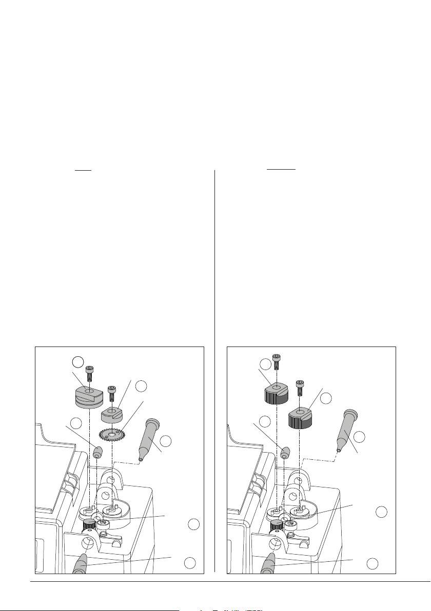
Changing Guide Kits
Assemble the counter wheel (1).
Insert the intermediate nozzle (2) until its collar
rests against the housing and tighten the screw.
Assemble the inlet nozzle (3).
Assemble the guide wheel* (4) and tighten the
screw.
Assemble the blade first, then mount the blade
clamp (5) onto the same axis and tighten the
screw. Caution: handle the blade carefully to
avoid injury.
Insert the guide set (6).
Assembly with Solder Wire Perforation:
Assembly without Solder Wire Perforation:
Changing Wheels and Blade
For this operation, disconnect the device from the mains. Disconnect the tool from the control unit
and open its cover.
Use the Allen key and the spanner, provided with the station. First disassemble the guide tube (6), the
support and traction wheels, or the guide wheel, the blade and its clamp (4)+(5). Then, disassemble
the nozzles (2)+(3). Disassemble the counter wheel (1).
Assemble the counter wheel (1).
Insert the intermediate nozzle (2) until its collar
rests against the housing and tighten the screw.
Assemble the inlet nozzle (3).
Assemble the support wheel* (4) onto the axis
and tighten the screw.
Assemble the traction wheel (5) and tighten
the screw.
Insert the guide set (6).
Support
Wheel *
Traction
Wheel
Interm.
Nozzle
Inlet
Nozzle
Counter
Wheel
1
2
3
4
5
Inlet
Nozzle
Interm.
Nozzle
Blade
Blade
Clamp
Guide
Wheel *
Guide
Set
Guide
Set
Counter
Wheel
1
2
3
4
5
66
* wheel bears diameter marking
OK
OK
OK
OK
Blade
Blade Clamp
Inlet
Nozzle
Guide
Wheel*
Intermediate
Nozzle
Support
Wheel*
Traction
Wheel
Intermediate
Nozzle
Inlet
Nozzle
Counter
Wheel
Counter
Wheel
1
4
1
2
3
4
5
5
4
2
3
6
6
Guide
Set
Guide
Set
AP250
AL250
AL250
SF280
SF250
ALE250
AP250
AL250
AL250
SF280
SF250
ALE250
AP250
AL250
AL250
SF280
SF250
ALE250
AP250
AL250
AL250
SF280
SF250
ALE250
AP250
AL250
AL250
SF280
SF250
ALE250
AP250
AL250
AL250
SF280
SF250
ALE250
1
23
4
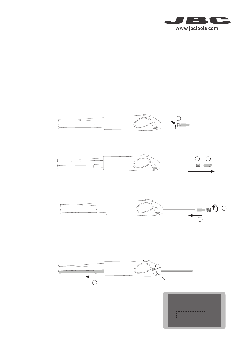
Outlet Nozzle Replacement
Flux can cause clogging at the outlet nozzle of the guide tube set and it can be necessary to replace
the worn or clogged outlet nozzle.
Note: There is a nozzle size for each soldering wire diameter. The use of the nozzle is necessary as
its inner diameter is adjusted to the solder wire diameter and guides the wire with greater precision.
To replace the outlet nozzle, follow these steps:
First, unload any remaining solder wire that might still be inside the guide tube (see pages XX and XX)
and then unplug the tool. Unscrew the spring inwards (2), following the downward direction of the spring.
Once the outlet nozzle is released from the spring, pull the outlet nozzle out (2) and then remove the
spring (3).
Place the new outlet nozzle onto the guide tube set (4) and then screw back the spring onto it to fix
the outlet nozzle onto the guide tube (5).
5
Guide Tube Replacement
To replace the guide tube, follow the outlet replacement steps until reaching no. 3. Once both the outlet
nozzle and the spring are removed, open the guide clamp knob (6) and remove the guide tube (7).
6
Guide Clamp Knob
Insert the new guide tube into the tool, close the guide clamp knob
to fix it in place and follow steps 4 and 5 to fix the outlet nozzle.
Enter “Tool Settings” at the SF control unit main menu and select
the proper wire diameter to complete the process.
7
Main MenuMain Menu
1 Reset settings
2
Station settings
3
Tool settings
4 Programs Settings
6
AP250
AL250
AL250
SF280
SF250
ALE250
AP250
AL250
AL250
SF280
SF250
ALE250
AP250
AL250
AL250
SF280
SF250
ALE250
AP250
AL250
AL250
SF280
SF250
ALE250
AP250
AL250
AL250
SF280
SF250
ALE250
AP250
AL250
AL250
SF280
SF250
ALE250
1
23
4
Outlet Nozzle Replacement
Flux can cause clogging at the outlet nozzle of the guide tube set and it can be necessary to replace
the worn or clogged outlet nozzle.
Note: There is a nozzle size for each soldering wire diameter. The use of the nozzle is necessary as
its inner diameter is adjusted to the solder wire diameter and guides the wire with greater precision.
To replace the outlet nozzle, follow these steps:
First, unload any remaining solder wire that might still be inside the guide tube (see pages XX and XX)
and then unplug the tool. Unscrew the spring inwards (2), following the downward direction of the spring.
Once the outlet nozzle is released from the spring, pull the outlet nozzle out (2) and then remove the
spring (3).
Place the new outlet nozzle onto the guide tube set (4) and then screw back the spring onto it to fix
the outlet nozzle onto the guide tube (5).
5
Guide Tube Replacement
To replace the guide tube, follow the outlet replacement steps until reaching no. 3. Once both the outlet
nozzle and the spring are removed, open the guide clamp knob (6) and remove the guide tube (7).
6
Guide Clamp Knob
Insert the new guide tube into the tool, close the guide clamp knob
to fix it in place and follow steps 4 and 5 to fix the outlet nozzle.
Enter “Tool Settings” at the SF control unit main menu and select
the proper wire diameter to complete the process.
7
Main Menu
Main Menu
1 Reset settings
2
Station settings
3
Tool settings
4 Programs Settings
First, unload any remaining solder wire that might still be inside the guide tube (see page 9) and then
unplug the tool. Unscrew the spring inwards (2), following the downward direction of the spring.
7
40 mm
50 mm
60 mm
80 mm
100 mm
130 mm
130 mm
para manuales - color gris
200 mm
300 mm