manual-gsf-guide-kit-0028099_ID-220219_EN.pdf - 第7页
AP250 AL250 AL250 SF280 SF250 ALE250 AP250 AL250 AL250 SF280 SF250 ALE250 AP250 AL250 AL250 SF280 SF250 ALE250 AP250 AL250 AL250 SF280 SF250 ALE250 AP250 AL250 AL250 SF280 SF250 ALE250 AP250 AL250 AL250 SF280 SF250 ALE25…
325
º
C
24.0
mm/s
25%
75%
Power
Con�nuous
50%
19:29
Sel. temp. 325
º
C
Ø 1.00 mm
Supplied: 12 mm
Language
Tool se�ngs
Counters
Reset
Exit
Feeder se�ngs
325
º
C
24.0
mm/s
25%
75%
Power
Con�nuous
50%
Sel. temp. 325
º
C
Ø 1.00 mm
Supplied: 12 mm
Tin reload process
Mode
Con�nuous
5.0mm/s
1.00mm
Off
None
Speed
Wire diameter
Feeder parameters lock
Backward
Back
325
º
C
24.0
mm/s
25%
75%
Power
Con�nuous
50%
Sel. temp. 325
º
C
Ø 1.00 mm
Supplied: 12 mm
Tin reload process
Forward
Backward
Place the �n on the gears
and press:
Press ok to exit
325
º
C
24.0
mm/s
25%
75%
Power
Con�nuous
50%
Sel. temp. 325
º
C
Ø 1.00 mm
Supplied: 12 mm
Program
Con�nuous
Discon�nuous
Mode
Back
0.5
mm/s
25%
75%
Power
Con�nuous
50%
19:29
Sel. Temp.
350
º
C
Ø 1.00 mm
Supplied: 0 mm
350
º
C
0.5
10.0
25%
75%
Power
Discon�nuous
50%
19:29
Sel. Temp.
350
º
C
Ø 1.00 mm
350
º
C
mm/s
mm
25%
75%
Power
50%
19:29
Sel. Temp.
350
º
C
350
º
C
3
2
1
Program #1
Ø 1.00 mm
325
º
C
24.0
mm/s
25%
75%
Power
Con�nuous
50%
Sel. temp. 325
º
C
Ø 1.00 mm
Supplied: 12 mm
Tin reload process
Mode
Con�nuous
20.0mm/s
1.00mm
Off
5.0mm
Speed
Wire diameter
Feeder parameters lock
Backward
Back
325
º
C
24.0
mm/s
25%
75%
Power
Con�nuous
50%
Sel. temp. 325
º
C
Ø 1.00 mm
Supplied: 12 mm
Feeder parameters lock
20.0mm/s
1.00mm
Off
5.0mm
Speed
Tin reload process
Wire diameter
Backward
Back
Mode
Con�nuous
325
º
C
24.0
mm/s
25%
75%
Power
Con�nuous
50%
Sel. temp. 325
º
C
Ø 1.00 mm
Supplied: 12 mm
Feeder parameters lock
1.00mm
Off
2.0mm
Edit program
Programs loaded
Set default programs
Tin reload process
Wire diameter
Backward
Back
Mode
Program
325
º
C
24.0
mm/s
25%
75%
Power
Con�nuous
50%
Sel. temp. 325
º
C
Ø 1.00 mm
Supplied: 12 mm
Edit program
Program #1
Length
Speed
3
2
1
mm
1.0
5.0
5.0
5.0
2.0
2.0
mm/s
325
º
C
24.0
mm/s
25%
75%
Power
Con�nuous
50%
Sel. temp. 325
º
C
Ø 1.00 mm
Supplied: 12 mm
Edit program
Length
Speed
3
2
1
mm
None
None
None
None
2.0
2.5
mm/s
Program #4
325
º
C
24.0
mm/s
25%
75%
Power
Con�nuous
50%
19:29
Sel. temp. 325
º
C
Ø 1.00 mm
Supplied: 12 mm
Language
Tool se�ngs
Counters
Reset
Exit
Feeder se�ngs
325
º
C
24.0
mm/s
25%
75%
Power
Con�nuous
50%
Sel. temp. 325
º
C
Ø 1.00 mm
Supplied: 12 mm
English
Deutsch
Español
Italiano
Français
日本語
한국어
Português
Pусский
325
º
C
24.0
mm/s
25%
75%
Power
Con�nuous
50%
Sel. temp. 325
º
C
Ø 1.00 mm
Supplied: 12 mm
Program version
8886732
Maximum temp
400
º
C
Off
200
º
C
On
º
C
mm
Minimum temp
Sound
PIN
Temp units
Length units
Sta�on reset
Back
325
º
C
24.0
mm/s
25%
75%
Power
Con�nuous
50%
Sel. temp. 325
º
C
Ø 1.00 mm
Supplied: 12 mm
Temp adjust
0
º
C
Temp level set
Off
10min
0min
150
º
C
Sleep delay
Peripher.
Sleep temp
Hiberna�on delay
Back
325
º
C
24.0
mm/s
25%
75%
Power
Con�nuous
50%
Sel. temp. 325
º
C
Ø 1.00 mm
Supplied: 12 mm
Plug hrs
28
Working hrs
Part
Tot
6
0
0
0
20
1
2
1
24
20
181
19
22786
118
Sleep hrs
Sleep cyc
Fed cyc
Fed mm
Hiber hrs
No tools hrs
325
º
C
24.0
mm/s
25%
75%
Power
Con�nuous
50%
Sel. temp. 325
º
C
Ø 1.00 mm
Supplied: 12 mm
Feeder parameters lock
20.0mm/s
1.00mm
12.0mm
Off
5.0mm
Speed
Tin reload process
Length
Wire diameter
Backward
Back
Mode
Discon�nuous
325
º
C
24.0
mm/s
25%
75%
Power
Con�nuous
50%
Sel. temp. 325
º
C
Ø 1.00 mm
Supplied: 12 mm
Tin reload process
Mode
Con�nuous
5.0mm/s
1.00mm
Off
None
Speed
Wire diameter
Feeder parameters lock
Backward
Back
325
º
C
24.0
mm/s
25%
75%
Power
Con�nuous
50%
Sel. temp. 325
º
C
Ø 1.00 mm
Supplied: 12 mm
1.00mm
Upda�ng
Your sta�ons is being updated
No
Do you want to update firmware?
Yes
EARTH FUSE F1.25 A
USE ONLY WITH A 250 V FUSE
EARTH FUSE F1.25 A
325
º
C
24.0
mm/s
25%
75%
Power
Con�nuous
50%
19:29
Sel. temp. 325
º
C
Ø 1.00 mm
Supplied: 12 mm
Language
Tool se�ngs
Counters
Reset
Exit
Feeder se�ngs
325
º
C
24.0
mm/s
25%
75%
Power
Con�nuous
50%
Sel. temp. 325
º
C
Ø 1.00 mm
Supplied: 12 mm
Tin reload process
Mode
Con�nuous
5.0mm/s
1.00mm
Off
None
Speed
Wire diameter
Feeder parameters lock
Backward
Back
325
º
C
24.0
mm/s
25%
75%
Power
Con�nuous
50%
Sel. temp. 325
º
C
Ø 1.00 mm
Supplied: 12 mm
Tin reload process
Forward
Backward
Place the �n on the gears
and press:
Press ok to exit
325
º
C
24.0
mm/s
25%
75%
Power
Con�nuous
50%
Sel. temp. 325
º
C
Ø 1.00 mm
Supplied: 12 mm
Program
Con�nuous
Discon�nuous
Mode
Back
0.5
mm/s
25%
75%
Power
Con�nuous
50%
19:29
Sel. Temp.
350
º
C
Ø 1.00 mm
Supplied: 0 mm
350
º
C
0.5
10.0
25%
75%
Power
Discon�nuous
50%
19:29
Sel. Temp.
350
º
C
Ø 1.00 mm
350
º
C
mm/s
mm
25%
75%
Power
50%
19:29
Sel. Temp.
350
º
C
350
º
C
3
2
1
Program #1
Ø 1.00 mm
325
º
C
24.0
mm/s
25%
75%
Power
Con�nuous
50%
Sel. temp. 325
º
C
Ø 1.00 mm
Supplied: 12 mm
Tin reload process
Mode
Con�nuous
20.0mm/s
1.00mm
Off
5.0mm
Speed
Wire diameter
Feeder parameters lock
Backward
Back
325
º
C
24.0
mm/s
25%
75%
Power
Con�nuous
50%
Sel. temp. 325
º
C
Ø 1.00 mm
Supplied: 12 mm
Feeder parameters lock
20.0mm/s
1.00mm
Off
5.0mm
Speed
Tin reload process
Wire diameter
Backward
Back
Mode
Con�nuous
325
º
C
24.0
mm/s
25%
75%
Power
Con�nuous
50%
Sel. temp. 325
º
C
Ø 1.00 mm
Supplied: 12 mm
Feeder parameters lock
1.00mm
Off
2.0mm
Edit program
Programs loaded
Set default programs
Tin reload process
Wire diameter
Backward
Back
Mode
Program
325
º
C
24.0
mm/s
25%
75%
Power
Con�nuous
50%
Sel. temp. 325
º
C
Ø 1.00 mm
Supplied: 12 mm
Edit program
Program #1
Length
Speed
3
2
1
mm
1.0
5.0
5.0
5.0
2.0
2.0
mm/s
325
º
C
24.0
mm/s
25%
75%
Power
Con�nuous
50%
Sel. temp. 325
º
C
Ø 1.00 mm
Supplied: 12 mm
Edit program
Length
Speed
3
2
1
mm
None
None
None
None
2.0
2.5
mm/s
Program #4
325
º
C
24.0
mm/s
25%
75%
Power
Con�nuous
50%
19:29
Sel. temp. 325
º
C
Ø 1.00 mm
Supplied: 12 mm
Language
Tool se�ngs
Counters
Reset
Exit
Feeder se�ngs
325
º
C
24.0
mm/s
25%
75%
Power
Con�nuous
50%
Sel. temp. 325
º
C
Ø 1.00 mm
Supplied: 12 mm
English
Deutsch
Español
Italiano
Français
日本語
한국어
Português
Pусский
325
º
C
24.0
mm/s
25%
75%
Power
Con�nuous
50%
Sel. temp. 325
º
C
Ø 1.00 mm
Supplied: 12 mm
Program version
8886732
Maximum temp
400
º
C
Off
200
º
C
On
º
C
mm
Minimum temp
Sound
PIN
Temp units
Length units
Sta�on reset
Back
325
º
C
24.0
mm/s
25%
75%
Power
Con�nuous
50%
Sel. temp. 325
º
C
Ø 1.00 mm
Supplied: 12 mm
Temp adjust
0
º
C
Temp level set
Off
10min
0min
150
º
C
Sleep delay
Peripher.
Sleep temp
Hiberna�on delay
Back
325
º
C
24.0
mm/s
25%
75%
Power
Con�nuous
50%
Sel. temp. 325
º
C
Ø 1.00 mm
Supplied: 12 mm
Plug hrs
28
Working hrs
Part
Tot
6
0
0
0
20
1
2
1
24
20
181
19
22786
118
Sleep hrs
Sleep cyc
Fed cyc
Fed mm
Hiber hrs
No tools hrs
325
º
C
24.0
mm/s
25%
75%
Power
Con�nuous
50%
Sel. temp. 325
º
C
Ø 1.00 mm
Supplied: 12 mm
Feeder parameters lock
20.0mm/s
1.00mm
12.0mm
Off
5.0mm
Speed
Tin reload process
Length
Wire diameter
Backward
Back
Mode
Discon�nuous
325
º
C
24.0
mm/s
25%
75%
Power
Con�nuous
50%
Sel. temp. 325
º
C
Ø 1.00 mm
Supplied: 12 mm
Tin reload process
Mode
Con�nuous
5.0mm/s
1.00mm
Off
None
Speed
Wire diameter
Feeder parameters lock
Backward
Back
325
º
C
24.0
mm/s
25%
75%
Power
Con�nuous
50%
Sel. temp. 325
º
C
Ø 1.00 mm
Supplied: 12 mm
1.00mm
Upda�ng
Your sta�ons is being updated
No
Do you want to update firmware?
Yes
EARTH FUSE F1.25 A
USE ONLY WITH A 250 V FUSE
EARTH FUSE F1.25 A
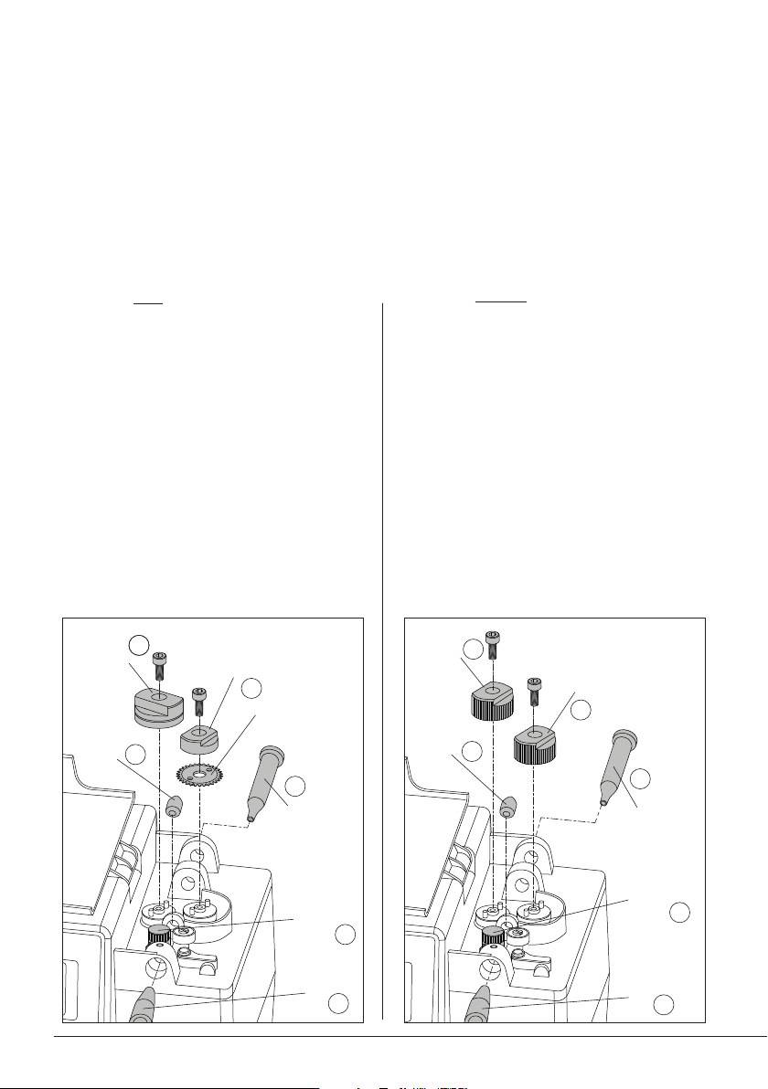
Changing Guide Kits
Assemble the counter wheel (1).
Insert the intermediate nozzle (2) until its collar
rests against the housing and tighten the screw.
Assemble the inlet nozzle (3).
Assemble the guide wheel* (4) and tighten the
screw.
Assemble the blade first, then mount the blade
clamp (5) onto the same axis and tighten the
screw. Caution: handle the blade carefully to
avoid injury.
Insert the guide set (6).
Assembly with Solder Wire Perforation:
Assembly without Solder Wire Perforation:
Changing Wheels and Blade
For this operation, disconnect the device from the mains. Disconnect the tool from the control unit
and open its cover.
Use the Allen key and the spanner, provided with the station. First disassemble the guide tube (6), the
support and traction wheels, or the guide wheel, the blade and its clamp (4)+(5). Then, disassemble
the nozzles (2)+(3). Disassemble the counter wheel (1).
Assemble the counter wheel (1).
Insert the intermediate nozzle (2) until its collar
rests against the housing and tighten the screw.
Assemble the inlet nozzle (3).
Assemble the support wheel* (4) onto the axis
and tighten the screw.
Assemble the traction wheel (5) and tighten
the screw.
Insert the guide set (6).
Support
Wheel *
Traction
Wheel
Interm.
Nozzle
Inlet
Nozzle
Counter
Wheel
1
2
3
4
5
Inlet
Nozzle
Interm.
Nozzle
Blade
Blade
Clamp
Guide
Wheel *
Guide
Set
Guide
Set
Counter
Wheel
1
2
3
4
5
66
* wheel bears diameter marking
OK
OK
OK
OK
Blade
Blade Clamp
Inlet
Nozzle
Guide
Wheel*
Intermediate
Nozzle
Support
Wheel*
Traction
Wheel
Intermediate
Nozzle
Inlet
Nozzle
Counter
Wheel
Counter
Wheel
1
4
1
2
3
4
5
5
4
2
3
6
6
Guide
Set
Guide
Set
AP250
AL250
AL250
SF280
SF250
ALE250
AP250
AL250
AL250
SF280
SF250
ALE250
AP250
AL250
AL250
SF280
SF250
ALE250
AP250
AL250
AL250
SF280
SF250
ALE250
AP250
AL250
AL250
SF280
SF250
ALE250
AP250
AL250
AL250
SF280
SF250
ALE250
1
23
4
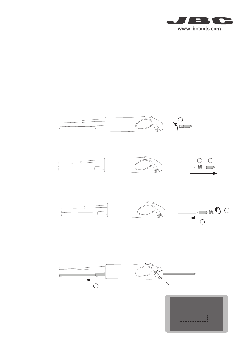
Outlet Nozzle Replacement
Flux can cause clogging at the outlet nozzle of the guide tube set and it can be necessary to replace
the worn or clogged outlet nozzle.
Note: There is a nozzle size for each soldering wire diameter. The use of the nozzle is necessary as
its inner diameter is adjusted to the solder wire diameter and guides the wire with greater precision.
To replace the outlet nozzle, follow these steps:
First, unload any remaining solder wire that might still be inside the guide tube (see pages XX and XX)
and then unplug the tool. Unscrew the spring inwards (2), following the downward direction of the spring.
Once the outlet nozzle is released from the spring, pull the outlet nozzle out (2) and then remove the
spring (3).
Place the new outlet nozzle onto the guide tube set (4) and then screw back the spring onto it to fix
the outlet nozzle onto the guide tube (5).
5
Guide Tube Replacement
To replace the guide tube, follow the outlet replacement steps until reaching no. 3. Once both the outlet
nozzle and the spring are removed, open the guide clamp knob (6) and remove the guide tube (7).
6
Guide Clamp Knob
Insert the new guide tube into the tool, close the guide clamp knob
to fix it in place and follow steps 4 and 5 to fix the outlet nozzle.
Enter “Tool Settings” at the SF control unit main menu and select
the proper wire diameter to complete the process.
7
Main MenuMain Menu
1 Reset settings
2
Station settings
3
Tool settings
4 Programs Settings
6
AP250
AL250
AL250
SF280
SF250
ALE250
AP250
AL250
AL250
SF280
SF250
ALE250
AP250
AL250
AL250
SF280
SF250
ALE250
AP250
AL250
AL250
SF280
SF250
ALE250
AP250
AL250
AL250
SF280
SF250
ALE250
AP250
AL250
AL250
SF280
SF250
ALE250
1
23
4
Outlet Nozzle Replacement
Flux can cause clogging at the outlet nozzle of the guide tube set and it can be necessary to replace
the worn or clogged outlet nozzle.
Note: There is a nozzle size for each soldering wire diameter. The use of the nozzle is necessary as
its inner diameter is adjusted to the solder wire diameter and guides the wire with greater precision.
To replace the outlet nozzle, follow these steps:
First, unload any remaining solder wire that might still be inside the guide tube (see pages XX and XX)
and then unplug the tool. Unscrew the spring inwards (2), following the downward direction of the spring.
Once the outlet nozzle is released from the spring, pull the outlet nozzle out (2) and then remove the
spring (3).
Place the new outlet nozzle onto the guide tube set (4) and then screw back the spring onto it to fix
the outlet nozzle onto the guide tube (5).
5
Guide Tube Replacement
To replace the guide tube, follow the outlet replacement steps until reaching no. 3. Once both the outlet
nozzle and the spring are removed, open the guide clamp knob (6) and remove the guide tube (7).
6
Guide Clamp Knob
Insert the new guide tube into the tool, close the guide clamp knob
to fix it in place and follow steps 4 and 5 to fix the outlet nozzle.
Enter “Tool Settings” at the SF control unit main menu and select
the proper wire diameter to complete the process.
7
Main Menu
Main Menu
1 Reset settings
2
Station settings
3
Tool settings
4 Programs Settings
First, unload any remaining solder wire that might still be inside the guide tube (see page 9) and then
unplug the tool. Unscrew the spring inwards (2), following the downward direction of the spring.
7
40 mm
50 mm
60 mm
80 mm
100 mm
130 mm
130 mm
para manuales - color gris
200 mm
300 mm
Main MenuMain Menu
5 Tin Reload Process
6 Counters
7 Software Version
1 Reset settings
2
Station settings
3
Tool settings
4 Programs Settings
ExitExit
Ba
ckward Forward
Reload ProcessReload Process
Press enter when nished
OK
OK
OK
OK
OK
OK
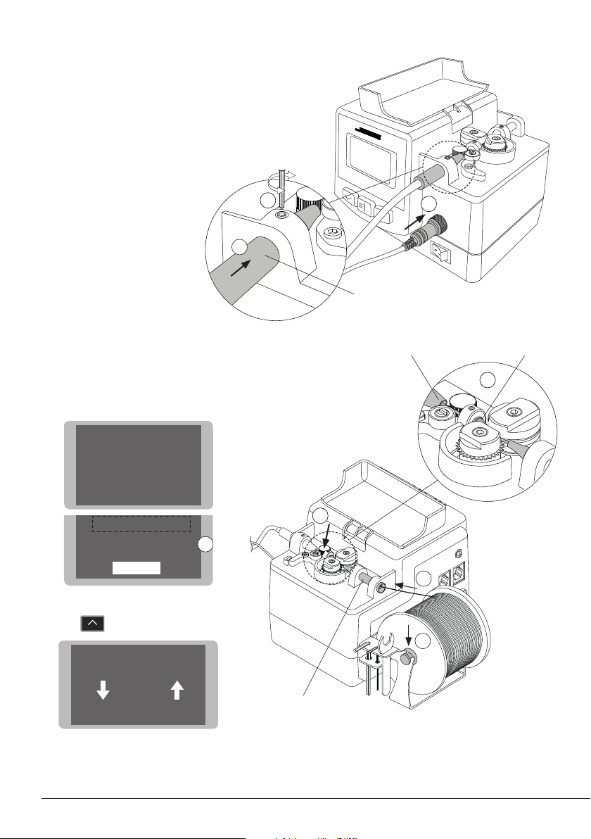
Tool Assembly
Connect the tool to the control unit following
this steps:
Insert and push the guide nozzle until the end
(1) and tighten the screw (2).
Connect the jack (3).
Solder Wire Loading
Put the solder reel into its support (1).
Introduce the solder wire into the inlet nozzle (2)
until it reaches the wheels (3).
Use the Tin Reload Process in the Main Menu (4).
The Relaod Procees screen opens.
Press to start the process.
Make sure the wire passes through the Interme-
diate Nozzle and enters into the Guide Tube (5).
1
3
Inlet
Nozzle
1
2
Insert to the end
4
Intermediate
Nozzle
To Guide Tube
2
3
5
8