manual-gsf-guide-kit-0028099_ID-220219_EN.pdf - 第8页
Main Menu Main Menu 5 Tin Reload Proc ess 6 Counters 7 Software Version 1 Reset settings 2 Station settings 3 T ool settings 4 Progr ams Settings Exit Exit Ba ckward Forward Reload Process Reload Process Press ent er whe…
AP250
AL250
AL250
SF280
SF250
ALE250
AP250
AL250
AL250
SF280
SF250
ALE250
AP250
AL250
AL250
SF280
SF250
ALE250
AP250
AL250
AL250
SF280
SF250
ALE250
AP250
AL250
AL250
SF280
SF250
ALE250
AP250
AL250
AL250
SF280
SF250
ALE250
1
23
4
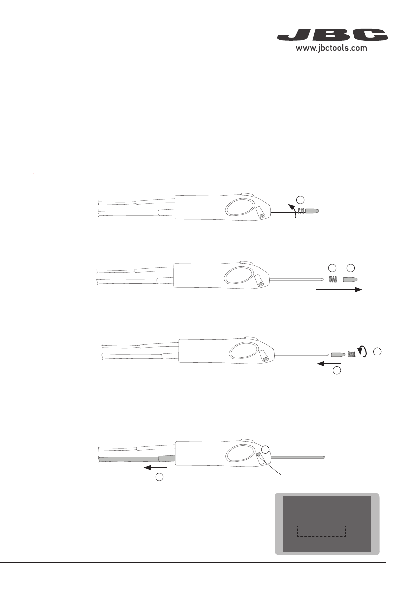
Outlet Nozzle Replacement
Flux can cause clogging at the outlet nozzle of the guide tube set and it can be necessary to replace
the worn or clogged outlet nozzle.
Note: There is a nozzle size for each soldering wire diameter. The use of the nozzle is necessary as
its inner diameter is adjusted to the solder wire diameter and guides the wire with greater precision.
To replace the outlet nozzle, follow these steps:
First, unload any remaining solder wire that might still be inside the guide tube (see pages XX and XX)
and then unplug the tool. Unscrew the spring inwards (2), following the downward direction of the spring.
Once the outlet nozzle is released from the spring, pull the outlet nozzle out (2) and then remove the
spring (3).
Place the new outlet nozzle onto the guide tube set (4) and then screw back the spring onto it to fix
the outlet nozzle onto the guide tube (5).
5
Guide Tube Replacement
To replace the guide tube, follow the outlet replacement steps until reaching no. 3. Once both the outlet
nozzle and the spring are removed, open the guide clamp knob (6) and remove the guide tube (7).
6
Guide Clamp Knob
Insert the new guide tube into the tool, close the guide clamp knob
to fix it in place and follow steps 4 and 5 to fix the outlet nozzle.
Enter “Tool Settings” at the SF control unit main menu and select
the proper wire diameter to complete the process.
7
Main Menu
Main Menu
1 Reset settings
2
Station settings
3
Tool settings
4 Programs Settings
First, unload any remaining solder wire that might still be inside the guide tube (see page 9) and then
unplug the tool. Unscrew the spring inwards (2), following the downward direction of the spring.
7
40 mm
50 mm
60 mm
80 mm
100 mm
130 mm
130 mm
para manuales - color gris
200 mm
300 mm
Main MenuMain Menu
5 Tin Reload Process
6 Counters
7 Software Version
1 Reset settings
2
Station settings
3
Tool settings
4 Programs Settings
ExitExit
Ba
ckward Forward
Reload ProcessReload Process
Press enter when nished
OK
OK
OK
OK
OK
OK
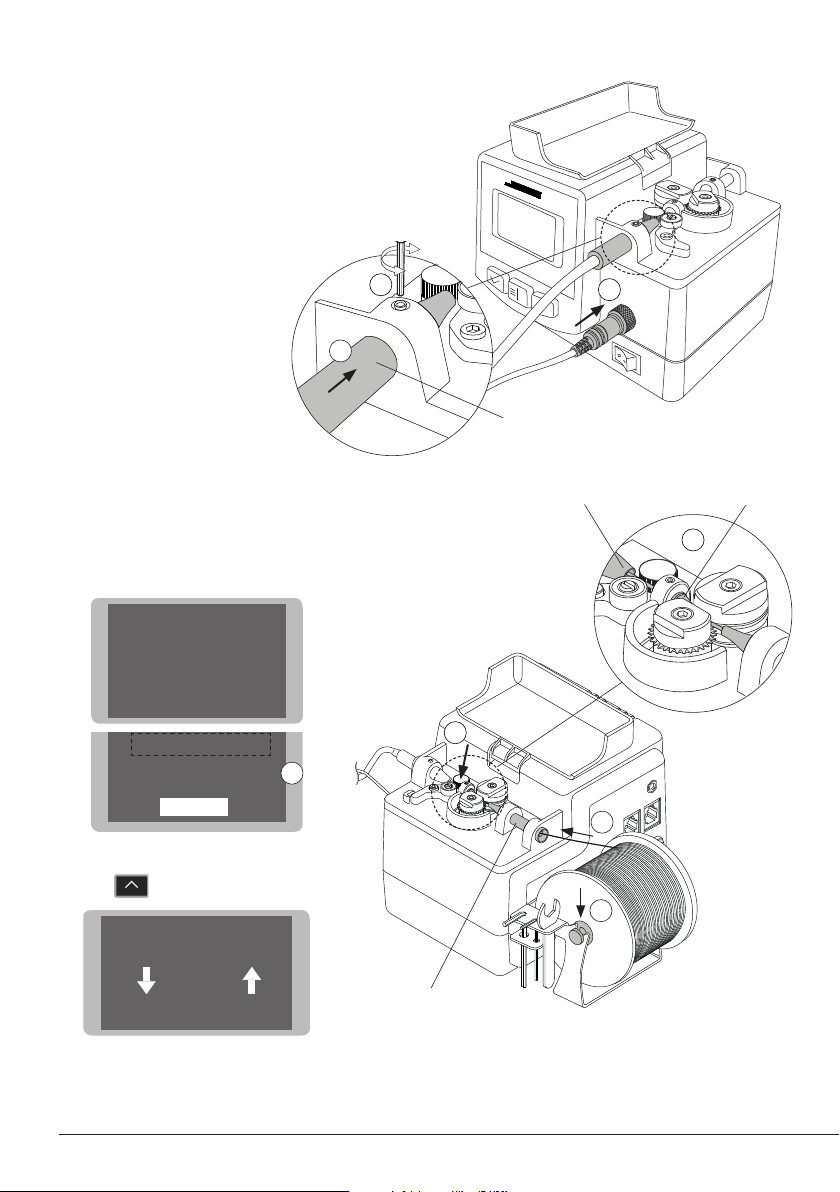
Tool Assembly
Connect the tool to the control unit following
this steps:
Insert and push the guide nozzle until the end
(1) and tighten the screw (2).
Connect the jack (3).
Solder Wire Loading
Put the solder reel into its support (1).
Introduce the solder wire into the inlet nozzle (2)
until it reaches the wheels (3).
Use the Tin Reload Process in the Main Menu (4).
The Relaod Procees screen opens.
Press to start the process.
Make sure the wire passes through the Interme-
diate Nozzle and enters into the Guide Tube (5).
1
3
Inlet
Nozzle
1
2
Insert to the end
4
Intermediate
Nozzle
To Guide Tube
2
3
5
8
OK
OK
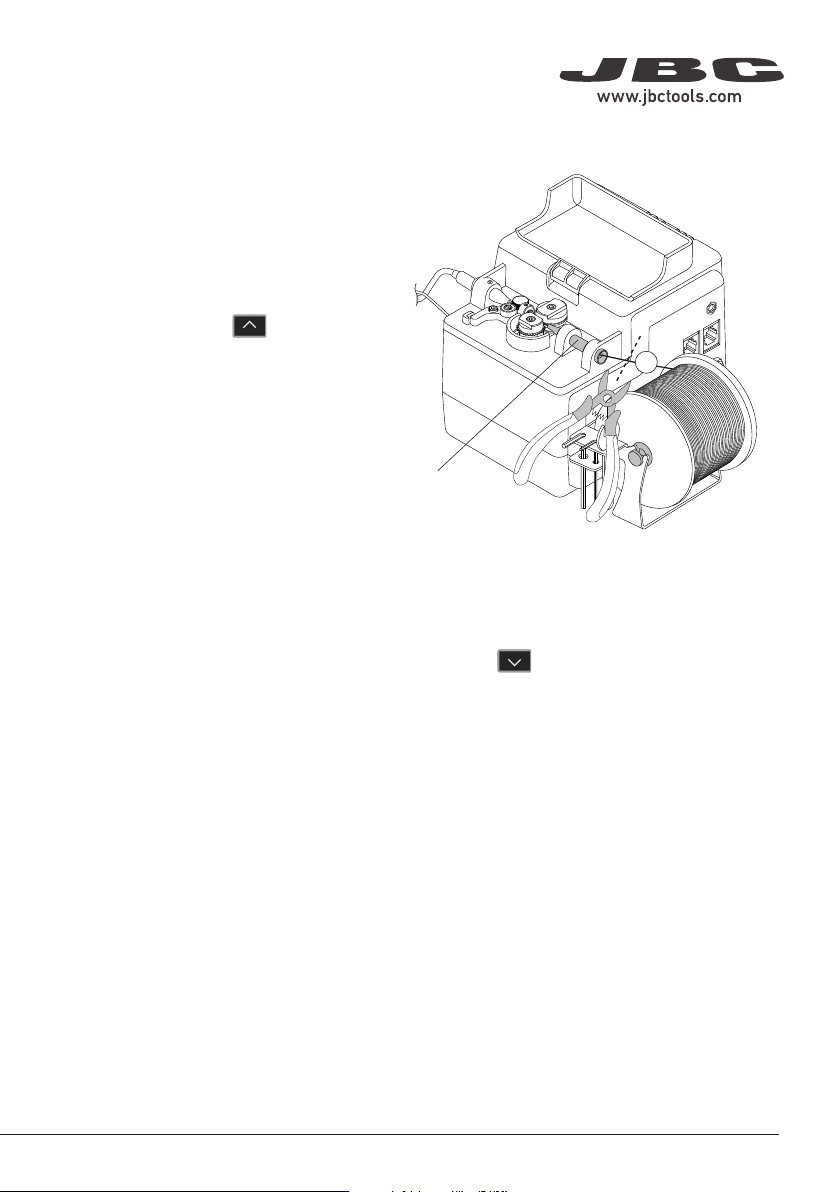
Solder-Wire Unloading
To unload solder wire with perforation that has
already passed through the guide tube, cut
the wire between the solder reel and the inlet
nozzle (1).
To extract the wire out of the tube, hold the tool
on your hand and press until the wire stops
moving forward.
Grasp the wire coming out of the outlet nozzle
with a pliers and pull from it until it is completely
out.
With Solder Wire Perforation
1
With Solder Wire Perforation
When using a guide kit without solder wire perforation, press until the wire is completely wound
on the solder reel to unload the solder wire. It is best to rotate the reel by hand as the wire is being
pulled back in order to keep it neatly arranged on the reel.
Or, If preferred, proceed as described before for perforated solder wire unloading.
Inlet
Nozzle
9
40 mm
50 mm
60 mm
80 mm
100 mm
130 mm
130 mm
para manuales - color gris
200 mm
300 mm