3OM-1343-008_w.pdf - 第103页
3-18 AKFEDT -ID 1.2.2 (A02) PEC Recognition Data (A02_01) PEC recognition function Select one of the following options to determine whether or not this function should be used. Disable : The PEC recognition function is n…

3-17
AKFEDT-ID
Note
(a) When "Enable" is set in the "U-N" or the "Block Sort" text box, the
automatic (delayed) recovery function cannot be used.
When "Priority of Comp." is specifi ed in the "Recovery Mode"
group box in the "Opn. Mode" tab sheet ("OPN. MODE" Window
(Submenu)), it is automatically changed to "Stop Auto Run (Priority
of Component Replenishment)" mode.
(b) When "Enable" is set in the "Block Sort" text box of the label
"Recovery regulation", it is invalidated unless the pattern program is
created to cope with the multi-model repetitive pattern function.
This is not regarded as an error during pattern program check
operation.
(c) When "Enable" is set in the "U-N" and "Block Sort" text boxes, only
"Enable" in the "Block Sort" text box becomes valid.
Sample Usage of This Function
•
Use this function when the adjoining pitch of components is "0.4
mm" or less.
There is an effect to prevent the interference between the components
to be placed and the already-placed components and the interference
between the already-placed components and the nozzles during
component placement operation.
•
Use this function when small components must be placed on the
placed large ones.
•
Use this function when the shielding cases, etc., must be attached to
the placed components.
0601-002
1.2 Operation Data

3-18
AKFEDT-ID
1.2.2 (A02) PEC Recognition Data
(A02_01)
PEC recognition function
Select one of the following options to determine whether or not this
function should be used.
Disable :
The PEC recognition function is not used.
Enable :
The PEC recognition function is used.
Notice
When the PEC recognition function is not used in a pattern program,
the program cannot be used.
(A02_02)
Correction algorithm
Select one of the following options as a correction algorithm.
Standard :
The method of least squares is specifi ed.
Mode #1 :
The midpoint correction is specifi ed.
(A02_03)
PEC recognition Mode
Global (Zones 1 through 5)
When "Enable" is set in the "PEC recognition Mode" text box, it is
required to select one of the following options as a global recognition
setting for each individual zones.
Disable :
The global recognition function is not activated.
1 Point :
The global recognition function is implemented, using
one fi ducial mark.
2 Point :
The global recognition function is implemented, using
two fi ducial marks.
3 Point :
The global recognition function is implemented, using
three fi ducial marks.
Note
(a) It is recommended that "2 Point" or more should be selected for the
global recognition.
(b) By dividing the area for the PEC recognition into several zones, it
became possible to correct a local expansion of a large PCB, etc.
0601-002
1.2 Operation Data
3-19
AKFEDT-ID
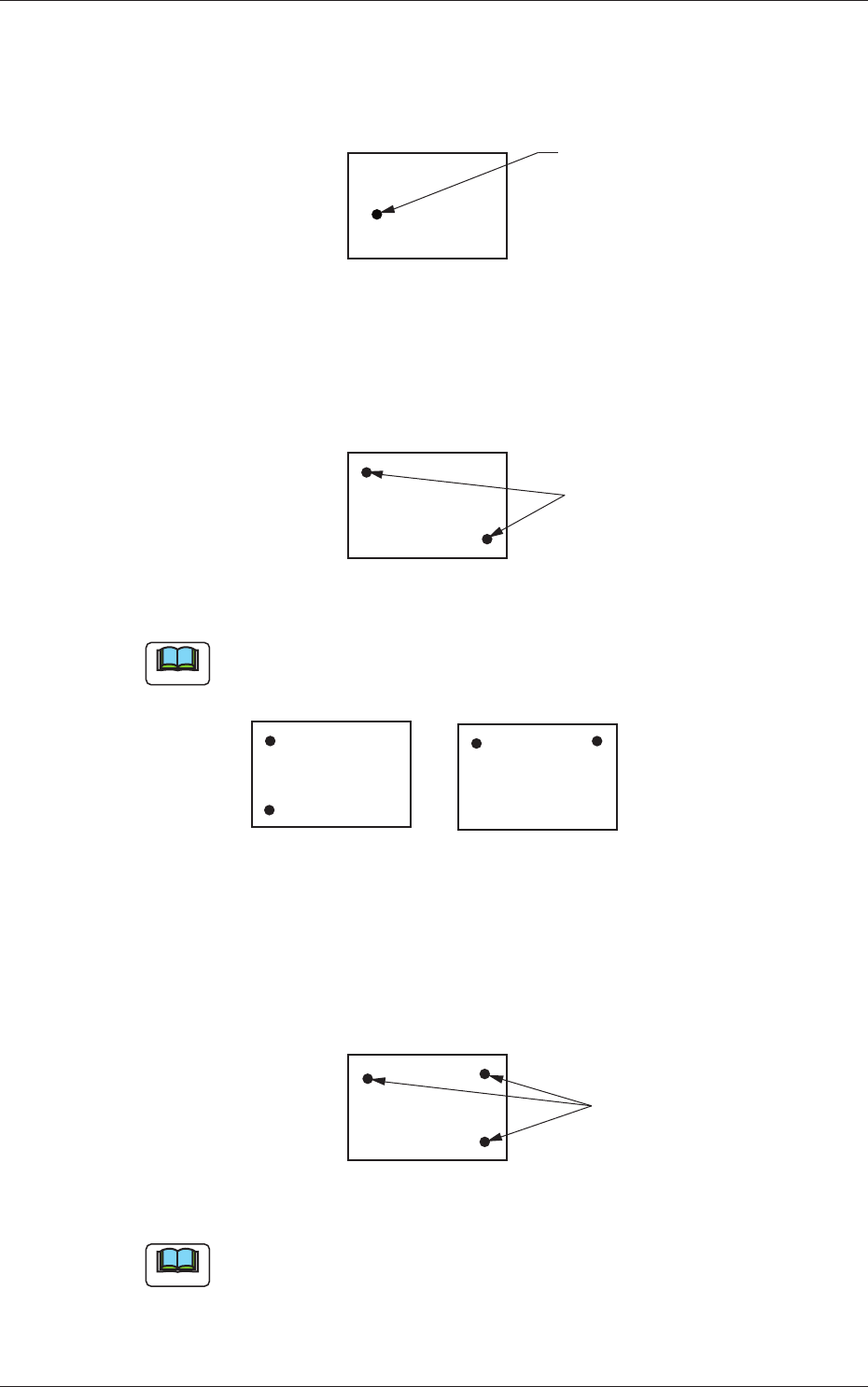
1-Point Recognition
Only the X and Y elements are corrected. The
θ
element (expansion,
etc.) is not corrected.
Fiducial Mark
Fig. 3C16
2-Point Recognition
Specify fi ducial mark positions so that one fi ducial mark is kept as
diagonally away from the other as possible.
Fiducial Marks
PCB
Fig. 3C17
Note
Avoid making positional relation such as fi ducial marks aligned vertically
or horizontally with each other as shown below.
Fig. 3C18
3-Point Recognition
Specify fi ducial mark positions so that the triangle are formed by
connecting the three points (three fi ducial marks) becomes as large as
possible.
Fiducial Marks
Fig. 3C19
Note
When any two of the three fi ducial marks are designated to be positioned
as close as possible to each other, the results of the correction will be
almost the same as "2-Point Recognition".
0601-002
1.2 Operation Data