3OM-1343-008_w.pdf - 第236页
6-5 AKFEDT -ID T able 3F3-2 T abs Description Fdr-B The corresponding tab sheet enables the operator to correct the variations, etc., for each individual feeders. Beam The corresponding tab sheet enables the operator to …
6-4
AKFEDT-ID
2.1 Device Offset Data
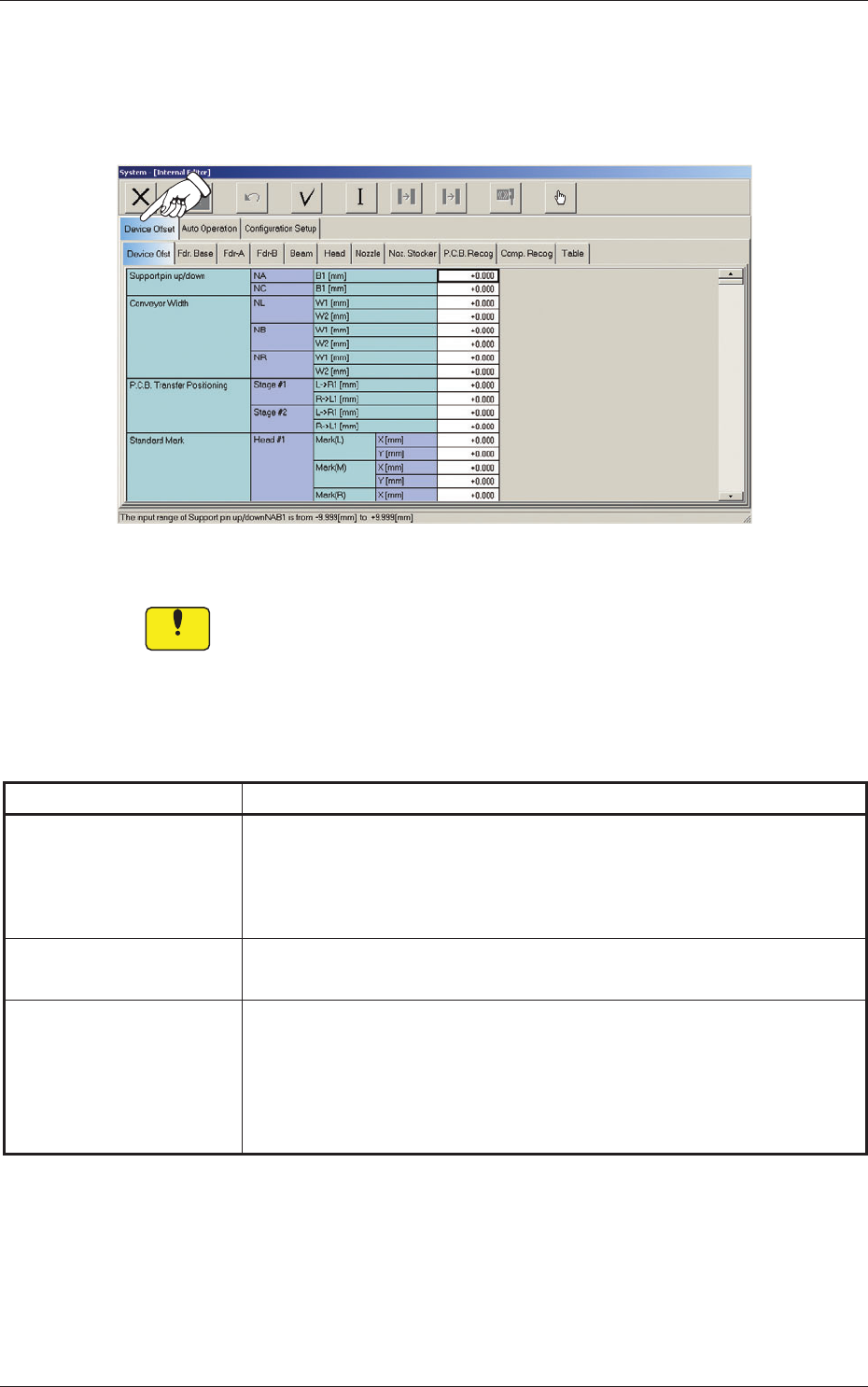
When the "Device Offset" tab is pressed in the "System - [Internal Editor]"
window, the following tab sheet appears.
Fig. 3F3 "Device Offset" Tab Sheet
Notice
Do not change the parameters unless necessary. These parameters
are factory-adjusted upon shipment of the machine.
The "Device Offset" tab is provided with the following tabs. When each tab
is pressed, the corresponding tab sheet appears.
Table 3F3-1
Tabs Description
Device Ofst
The corresponding tab sheet enables the operator to adjust the positional
and angular deviations based on the design dimensions representing the
X/Y beam driving X/Y coordinates viewed from the PCB positioning
X/Y coordinates.
Fdr. Base
The corresponding tab sheet enables the operator to adjust the deviations
based on the design values of each individual feeders.
Fdr-A
This offset data is used independently for the machine. The corresponding
tab sheet enables the operator to adjust the positional deviations (viewed
from the PCB positioning X and Y coordinates) based on the design
dimensions representing the feeder pickup position and height for each
individual feeder slot Nos. (Fdr Nos.).
0607-003
2.1 Device Offset Data

6-5
AKFEDT-ID
Table 3F3-2
Tabs Description
Fdr-B
The corresponding tab sheet enables the operator to correct the variations,
etc., for each individual feeders.
Beam
The corresponding tab sheet enables the operator to correct the positional
and angular deviations based on the design dimension (the distance
between the placement reference coordinate origin and the center of the
PEC recognition camera at the head origin).
Head
The corresponding tab sheet enables the operator to correct the positional
deviation (placement coordinates) caused due to the deviation of
straightness (skew) of each individual head up/down axis guides and set
up the offset data for the distance between the scanning coordinate center
of the PEC camera and the head rotational center.
Nozzle
The corresponding tab sheet enables the operator to adjust the deviations
in height and rotational center of each nozzle and set the measured values
of the master nozzle (reference nozzle).
Noz. Stocker
The corresponding tab sheet enables the operator to set the offset data
for adjustment (not available yet) of positional deviations compared with
the design dimensions of the nozzle stocker unit position (viewed from
the PCB positioning reference) and the offset data for adjustment of
positional deviations compared with the design dimensions (viewed from
the PCB positioning reference) for each individual addresses 1 through
12 of 1-1 to 4-4.
PCB Recog
The corresponding tab sheet enables the operator to adjust the horizontal
swing (tilt) of the PEC recognition camera.
Comp. Recog
The corresponding tab sheet enables the operator to set the offset data
that will be used to adjust the positional deviation based on the design
dimension (the distance between the machine reference coordinate origin
and the center of the component recognition camera).
Table
The corresponding tab sheet enables the operator to set the amount of
deviation based on the specifi ed distance when each head (Heads 1
through 4) has moved as far as the specifi ed distance (each grid point)
from the PCB positioning reference.
0607-003
2.1 Device Offset Data

6-6
AKFEDT-ID
0607-003
2.1.1 Device Offset
When the "Device Ofst" tab is pressed in the "Device Offset" tab sheet, the
following tab sheet appears.
[1]
[2]
[3]
Fig. 3F4 "Device Offset" Tab Sheet (1)
[4]
Fig. 3F5 "Device Offset" Tab Sheet (2)
2.1 Device Offset Data