3OM-1343-008_w.pdf - 第244页
6-13 AKFEDT -ID 2.1.3 Feeder Offset A and Feeder Offset B When the "Fdr-A" or the "Fdr -B" tab is pressed in the "Device Of fset" tab sheet, the corresponding tab sheet appears as shown belo…

6-12
AKFEDT-ID
[3] Mark (Right)
X (Horizontal), Y (Vertical) [mm]
The set offset parameters are used to adjust the positional deviations
based on the design dimensions of Feeder Bases #1, #2, #3, and #4 (Rear
Side: #1 and #3, Front Side: #2 and #4). The values based on the PL-
XY coordinate system must be entered in the text boxes.
As for "Mark (Right) X and Y", the positional deviations are calculated
with the feeder base offset measurement jig being set on the right end of
the feeder base through recognition with the PEC recognition camera.
[4] Mark (Right)
L (Height) [mm]
The set offset parameters are used to adjust the positional deviations
(height direction) based on the design dimensions of Feeder Bases #1,
#2, #3, and #4 (Rear Side: #1 and #3, Front Side: #2 and #4).
When the feeder bases are installed lower than the design values, a plus
value must be entered in each text box.
Note
The tilts of the PCB positioning sections on the feeder base sections are
calculated on the X and Y values of "Mark (Left)" and "Mark (Right)"
2.1 Device Offset Data
0601-002
6-13
AKFEDT-ID
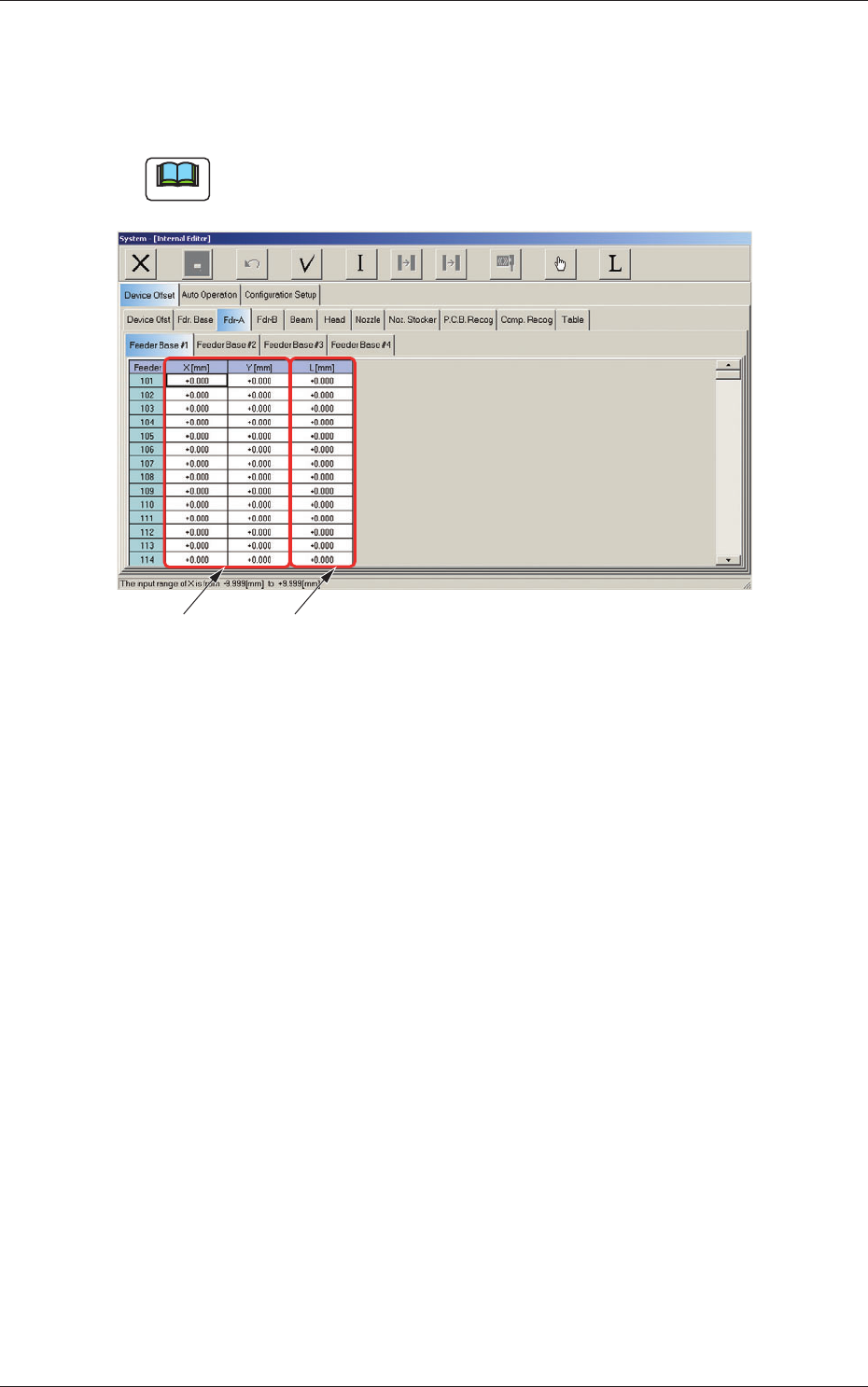
2.1.3 Feeder Offset A and Feeder Offset B
When the "Fdr-A" or the "Fdr-B" tab is pressed in the "Device Offset" tab
sheet, the corresponding tab sheet appears as shown below.
Note
Another tab sheet can be opened by pressing the corresponding "Feeder
Base" tab.
[1] [2]
Fig. 3F12
"
Fdr-A
"
Tab Sheet
Feeder Offset A
This offset data is used to correct variation in each feeder slot (Fdr No.) of
the feeder base.
•
The parameters measured at shipment of the machine are entered.
Do not change the parameters unless necessary.
Feeder Offset B
This offset data is used to correct variation in the feeder.
•
The X and Y parameters are recognition-processed during the automatic
operation to track the positional relation between the nozzle and component
centers and updated automatically for better pickup posture (pickup on the
component center).
Note:
In normal cases, it is not necessary to enter any parameters.
•
The "L [mm]" parameters are not updated automatically but the entered
ones are refl ected.
2.1 Device Offset Data
0607-003

6-14
AKFEDT-ID
Feeder offset parameters are added to actual offset values.
Actual Offset Values = Feeder (A) Offset + Feeder (B) Offset
Note
Perform the same operations for the feeders (Feeder Base #1: 101 to 150,
#2: 201 to 250, #3: 301 to 350, and #4: 401 to 450) on each feeder base at
the "Feeder Base #1" through "Feeder Base #4" tab sheets.
Offset Parameters
Set the following offset values for each individual feeders (Feeder Base
#1: 101 to 150, #2: 201 to 250, #3: 301 to 350, and #4: 401 to 450).
2.1 Device Offset Data
0601-002