3OM-1343-008_w.pdf - 第126页
3-41 AKFEDT -ID (D02_04) P-No. Shown are the step Nos. of the placement data (P). Set coordinates and angles for component placement in the lines of the step Nos. (P-Nos.). (D02_05) X [mm] and Y [mm] Set Coordinates X an…
3-40
AKFEDT-ID
(D02_03)
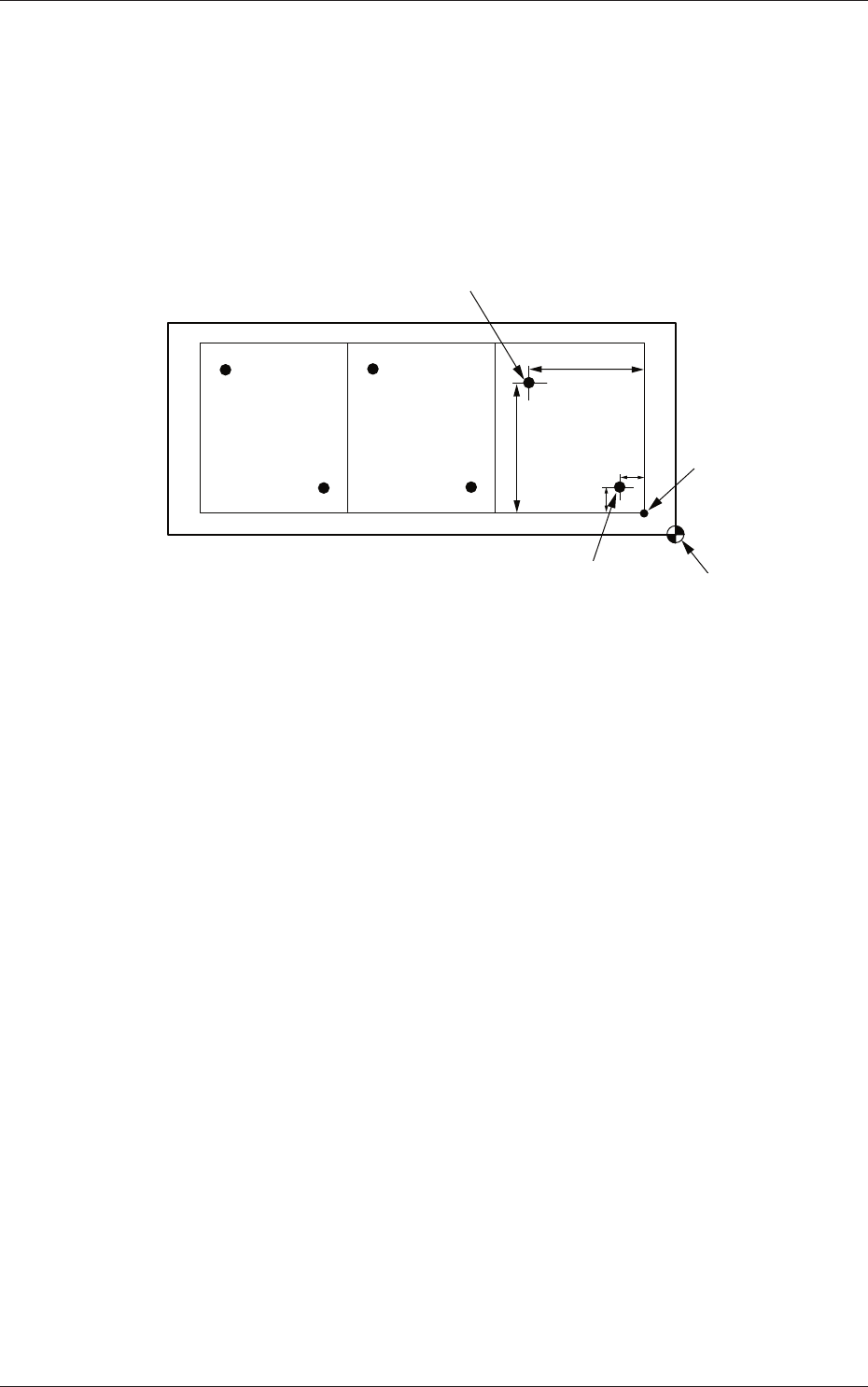
Unit PCB Fiducial
Select one of the following options to determine whether or not the unit
PCB BBR function should be used.
Disable :
The unit PCB BBR function is not used.
Enable :
The unit PCB BBR function (2-point recognition) is used.
Y
1
X
2
Y
2
X
1
Second Fiducial Mark
Pattern Origin
First Fiducial Mark
Placement Coordinate
Reference
Fig. 3C29 Example of Unit PCB BBR Recognition
Recog Coord X1 [mm] and Recog Coord Y1 [mm]
Set the X1 and Y1 coordinates of the fi rst fi ducial mark based on the
pattern origin.
Recog Coord X2 [mm] and Recog Coord Y2 [mm]
Set the X2 and Y2 coordinates of the second fi ducial mark based on the
pattern origin.
Fiducial Mark FM1 and Fiducial Mark FM2
Set the mark Nos. of the fi rst and second fi ducial marks FM1 and FM2.
Select the mark Nos. (Mark Codes) specifi ed in the PEC recognition
mark data of the operation data.
0601-002
1.5 Placement Data
3-41
AKFEDT-ID
(D02_04)
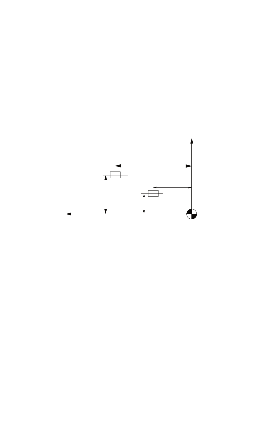
P-No.
Shown are the step Nos. of the placement data (P).
Set coordinates and angles for component placement in the lines of the
step Nos. (P-Nos.).
(D02_05)
X [mm] and Y [mm]
Set Coordinates X and Y for component placement.
The coordinates must be based on the placement coordinate reference
(N
0
).
Y2
Y1
X1
X2
Y
X
Placement Coordinate Reference (N
0)
Fig. 3C30
0601-002
1.5 Placement Data
3-42
AKFEDT-ID
(D02_06)
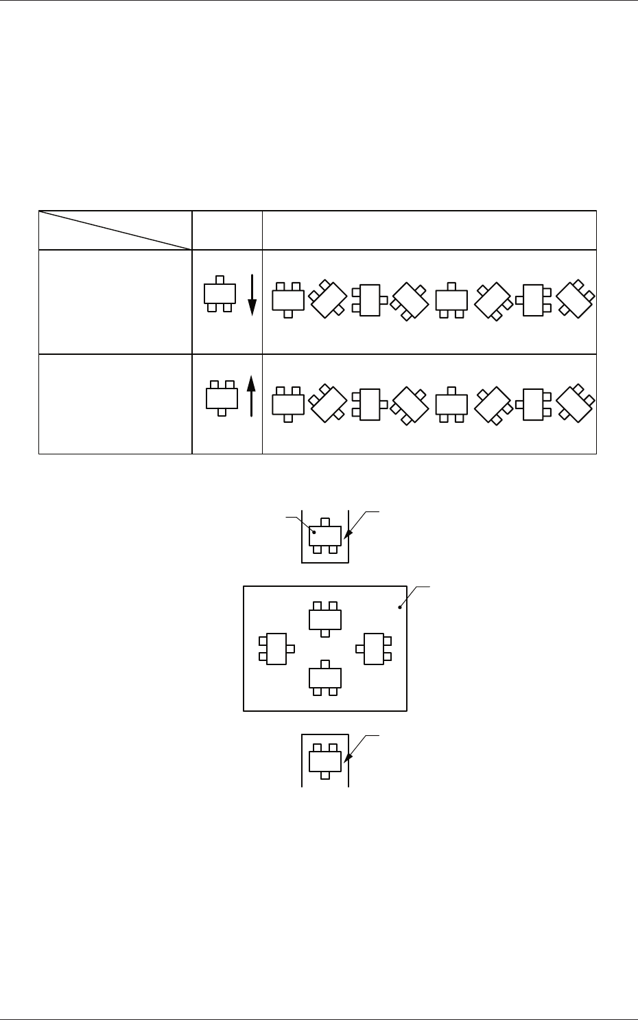
Z=theta [deg]
Set angles for component placement.
The placement angles must be determined according to the packaged
posture of components on the tape feeder.
Example:
0o 45o 90o 135o 180o 225o 270o 315o
Front Side of Machine
Z=Theta
(Angle)
Feeder Bases #1
and #3
Packaged
Posture
User Direction
of Tape Feed
Packaged
Posture
User Direction
of Tape Feed
Feeder Bases #2
and #4
Rear Side of Machine
Packaged Posture of
Component on Feeder
Tape Feeder
PCB
Tape Feeder
0o
90o
180o
270o
Fig. 3C31
0601-002
1.5 Placement Data