TM2596.Functional Specification of Mount Group Number.pdf - 第9页
SMT Software En gineering Group IMOperations YAMAHAMOTORCO.,LTD. MD OC-SOFT50106 9/11 5.2 Group ID and Group Order These parameter s are set a utom atically b y executing N o zzle Interf erence C…
SMT Software Engineering Group
IMOperationsYAMAHAMOTORCO.,LTD.
MDOC-SOFT50106
8/11
5. Additional item of Board Data
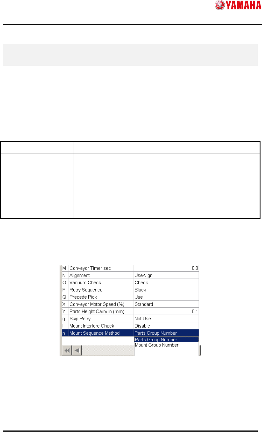
5.1 Mount Sequence Method
“Mount Sequence Method” has been added to board data. You can specify either “Parts Group
Number” or “Mount Group Number”.
Table5.1 Mount Sequence Method
Mount Sequence Method
Explanation
Parts Group Number Controls a mounting order for each parts.
Specify a mounting order manually.
Mount Group Number Controls a mounting order for each mounting point.
Optimization results (cycle time) will improve compared with “Parts
Group Number”.
But mounting order may not be specified manually.
Confirmation and edit of the setting of “Mount Sequence Method” are possible in [Board] –
[Board].
Fig5.1 Mount Sequence Method
SMT Software Engineering Group
IMOperationsYAMAHAMOTORCO.,LTD.
MDOC-SOFT50106
9/11
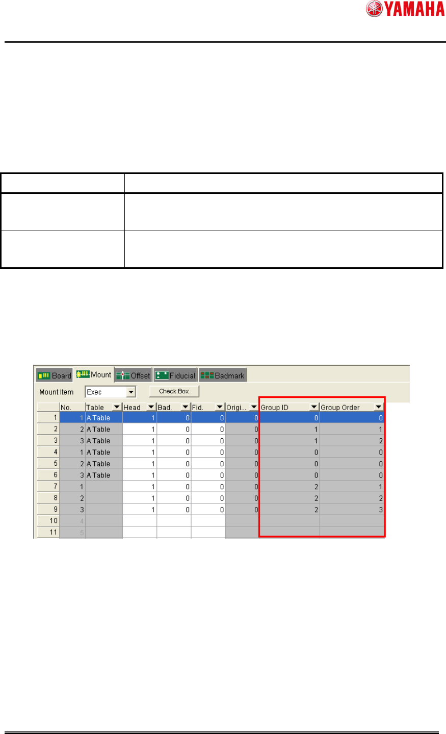
5.2 Group ID and Group Order
These parameters are set automatically by executing Nozzle Interference Check.
These parameters may not be edited.
Table5.2 Group ID and Group Order
Item Name Explanation
Group ID Indicates groups of mounting points under the control of mounting
order.
Group Order Indicates the number of mounting order among the mounting points
of the same Group ID.
Note: As for a mounting point whose Group ID and Group Order are 0, mounting order control of
each mounting point becomes invalid.
Confirmation of the setting of “Group ID” and “Group Order” is possible in [Board] – [Mount].
These setting may not be edited.
Fig5.2 Group ID and Group Order
SMT Software Engineering Group
IMOperationsYAMAHAMOTORCO.,LTD.
MDOC-SOFT50106
10/11
6. Codicil: About arranging Mounting Order
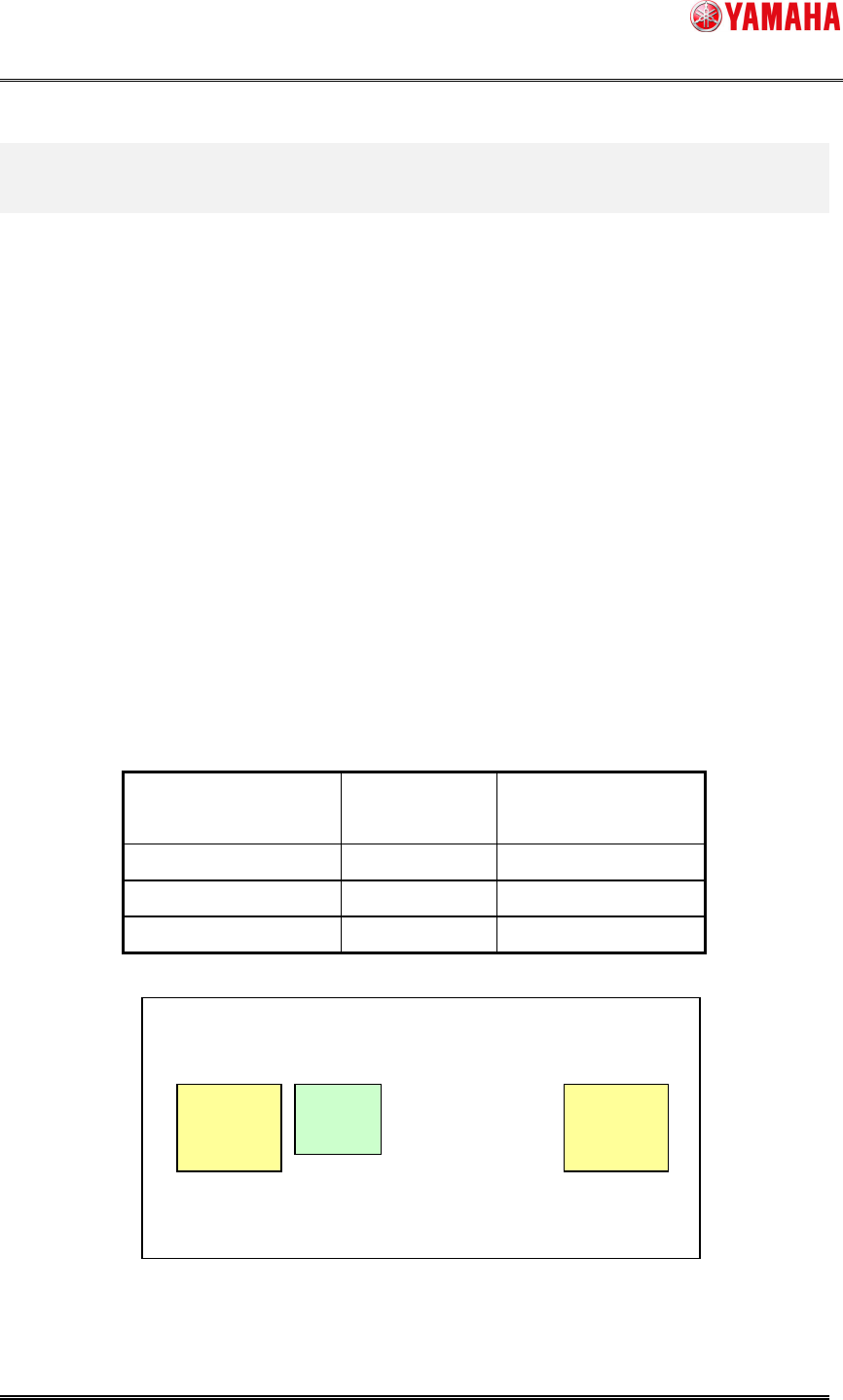
6.1 Arranging Mounting Order with “Parts Group Number”
It explains a case using a part of three mounting points and using two kinds of parts as fig.6.1.
Because the mounting space is small between the mounting points “A1” and “B1”, mounting on
“A1” should be prior to on “B1” to avoid interference. Therefore the value of “Parts Group No.”
should be set as follows.
Parts Name: “A”, Parts Group No: “1”
Parts Name: “B”, Parts Group No: “2”
By this setting, although there is no parts to interfere near the mounting point “B2”, a mounting
order is assigned to “B2” as “Parts Group No. 2”
When the optimization is executed with this board data, the mounting order becomes
“A1->B1->B2” even if “B2->A1->B1” should be faster.
Table6.1 Mount Information and Parts Information
Mount Point Name Parts Name Parts Group No.
(in Parts Information)
A1 A 1
B1 B 2
B2 B 2
Fig6.1 Parts Group Number
B1
A1
B2
Order:1
Order:2
Order:2