00193889-0302_AI_LP-Ausrichtung_DE+EN.pdf - 第35页
Fitted spacer and ‘pat h limiter slat ’ Threaded hole PCB alignment unit for SIPLACE S-27 HM / HS-60 / HF-series / X-series / D-series Edition 11/2006 33 2 Fig. 2 - 2 Fitted path limiter by example for D1 / D2 2 Fig. 2 -…
PCB alignment unit for SIPLACE S-27 HM / HS-60 / HF-series / X-series / D-series
Edition 11/2006
32
: Disassembly the lifting table.
: Fix the block/spacer colocate with ‘path limiter slat
’ on the end face of the lifting table.
2
On S-27 HM, this path limiter is L-shaped.
Fit it with the longer limb at the top. 2
Hole for path limiter
Fitted path limiter
2
2
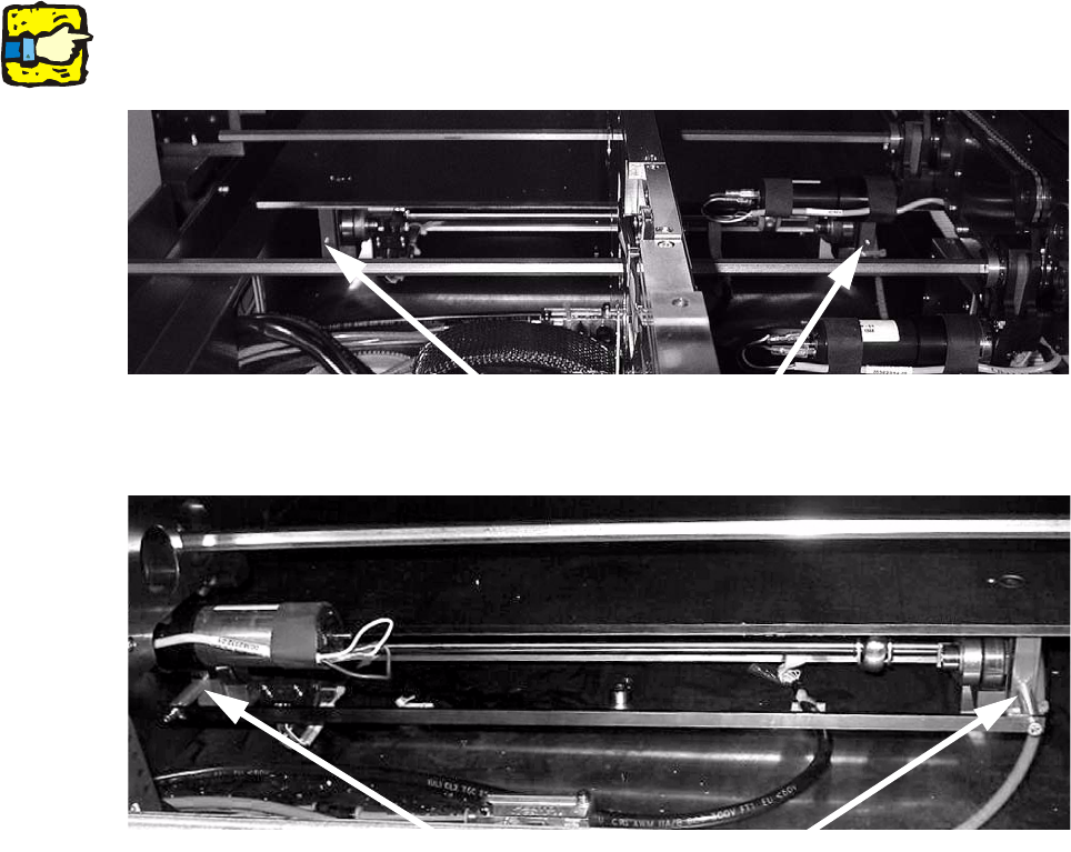
Fig. 2 - 1 Sample picture from HS-60 placement area 1 (similar to other conveyor types)
Fitted spacer and
‘path limiter slat’
Threaded hole
PCB alignment unit for SIPLACE S-27 HM / HS-60 / HF-series / X-series / D-series
Edition 11/2006
33
2
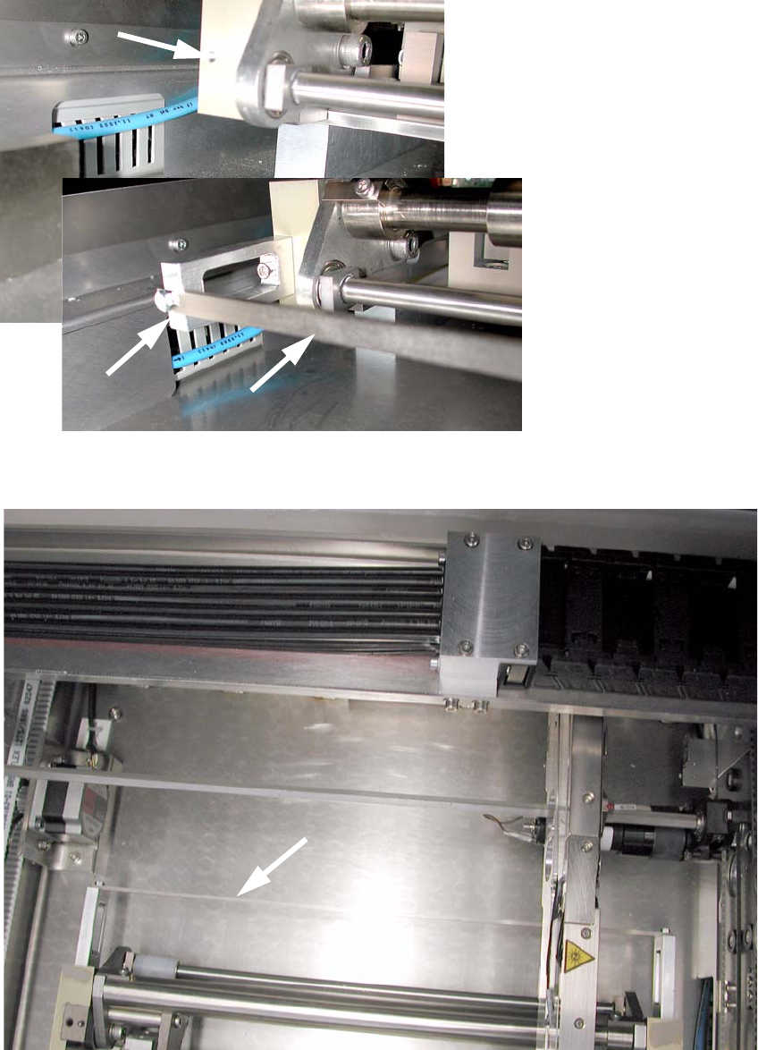
Fig. 2 - 2 Fitted path limiter by example for D1 / D2
2
Fig. 2 - 3 Top view on ‘path limiter slat’ e.g. D1 / D2
PCB alignment unit for SIPLACE S-27 HM / HS-60 / HF-series / X-series / D-series
Edition 11/2006
34
: Remove the cover plate from the conversion board (4 screws).
: Plug the coding switches (1 switch per conv
eyor track) into slots X36 and X37 on the
conversion board assembly tray (00359425- or 0035
9426-) (see Fig. 2 - 4 to Fig. 2 - 10).
The conversion board may be located in the middle of the conveyor (HS-60, HF, X) or in the
inpu
t area (S-27 HM) beneath a cover plate, depending on the type of machine.
2
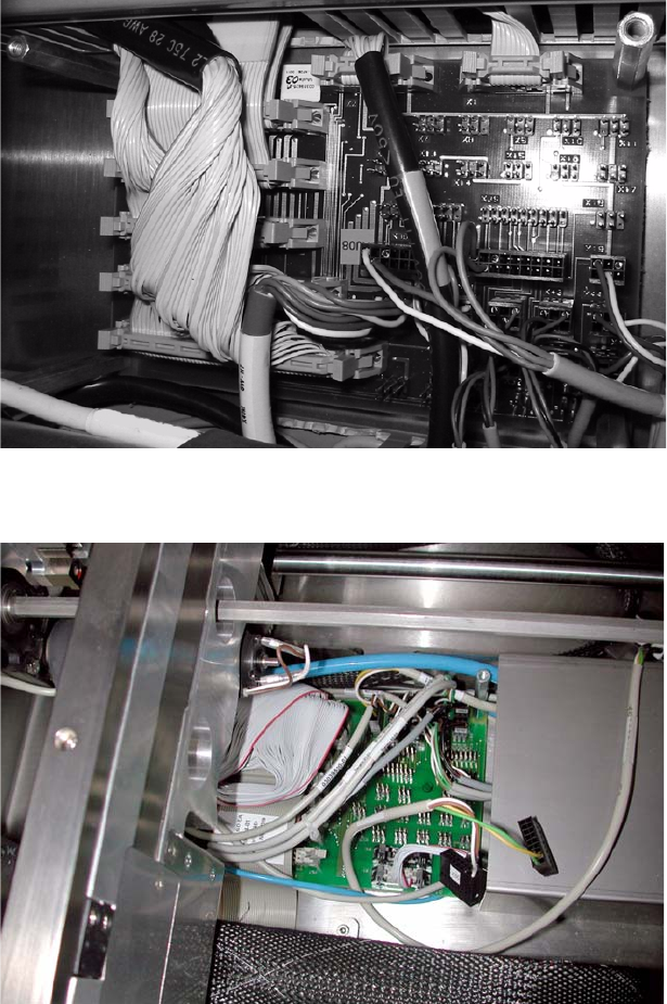
Fig. 2 - 4 Conversion board as example HS-60 (other conveyors similar)
2
Fig. 2 - 5 Conversion board as example D1 / D2