00193889-0302_AI_LP-Ausrichtung_DE+EN.pdf - 第39页
PCB alignment unit for SIPLACE S-27 HM / HS-60 / HF-series / X-series / D-series Edition 11/2006 37 2 Fig. 2 - 10 Conversion board HS-60 / HF / D3 / D4 (00 359425-) : Carry the cables along the ribbon cable (see Fig. 2 -…
PCB alignment unit for SIPLACE S-27 HM / HS-60 / HF-series / X-series / D-series
Edition 11/2006
36
2
Fig. 2 - 8 HS-60 / D4
2
Fig. 2 - 9 HF-series / X-series / D3
PCB alignment unit for SIPLACE S-27 HM / HS-60 / HF-series / X-series / D-series
Edition 11/2006
37
2
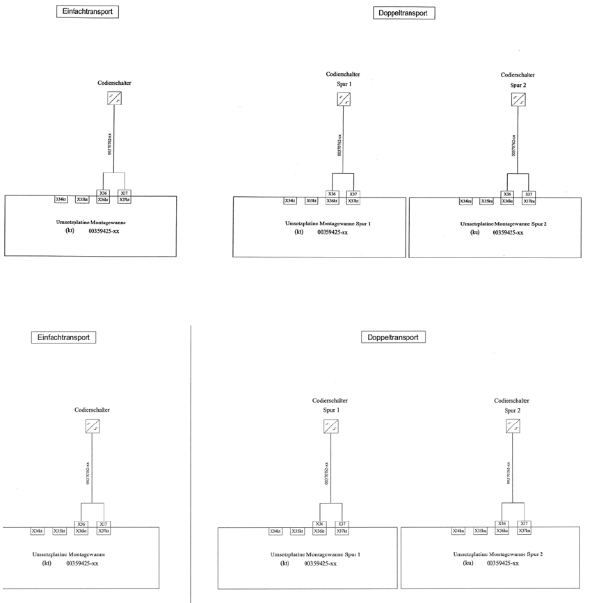
Fig. 2 - 10 Conversion board HS-60 / HF / D3 / D4 (00359425-)
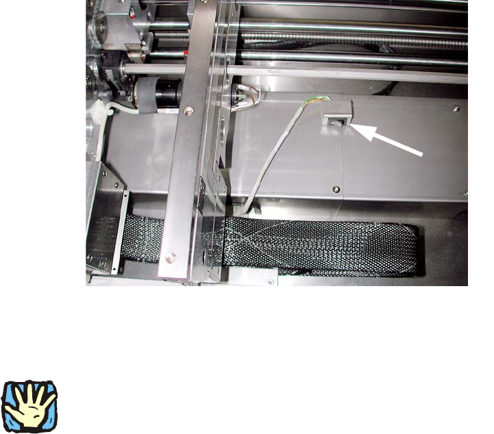
: Carry the cables along the ribbon cable (see Fig. 2 - 11 and Fig. 2 - 12).
: Put the cover plate on it.
: Add the coding switch to the cover plate and fix both.
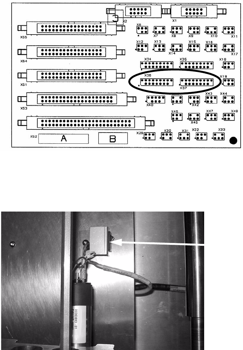
Fig. 2 - 11 Example of a coding switch from HS-60, other conveyors are similar
Coding switch
PCB alignment unit for SIPLACE S-27 HM / HS-60 / HF-series / X-series / D-series
Edition 11/2006
38
2
Fig. 2 - 12 Example of a coding switch from D1 / D2
The coding switch allows the operator to determine whether the PCB alignment option should be
used or not. 2
2
If the option is disabled, the ‘stopper PCB adjustment’ must be removed since, in this case, the
conveyor control will not detect the stop, which could result in a crash when the conveyor side
walls are moved. 2
If this switch is active, a warning is displaye
d on screen as they move together: 2
Transport error: 15429 Warning: Conveyor
belt moving together with installed option—Pick-up
side: Conv. EC:8
Wait for handling data 2
: Fit the lifting table bed in the conveyor once more.
2