ANSI ESD-S20.20-2021-EN.pdf - 第14页
ANSI/ESD S20.20- 2021 6 Table 2. Personnel Grounding Requirement Technical Requirement Product Qualification Compliance Verificatio n Test Method(s) Required Limit (s) Test Method(s) Required Limit (s) Wrist Strap System…
ANSI/ESD S20.20-2021
5
There are no requirements for a compliance verification plan for testing the grounding system; only
initial verification is required. If ground fault circuit interrupters (GFCI) are installed at the user's
facility, this measurement is not required.
NOTE: Verification of the grounding system should be considered after electrical system maintenance or
service additions.
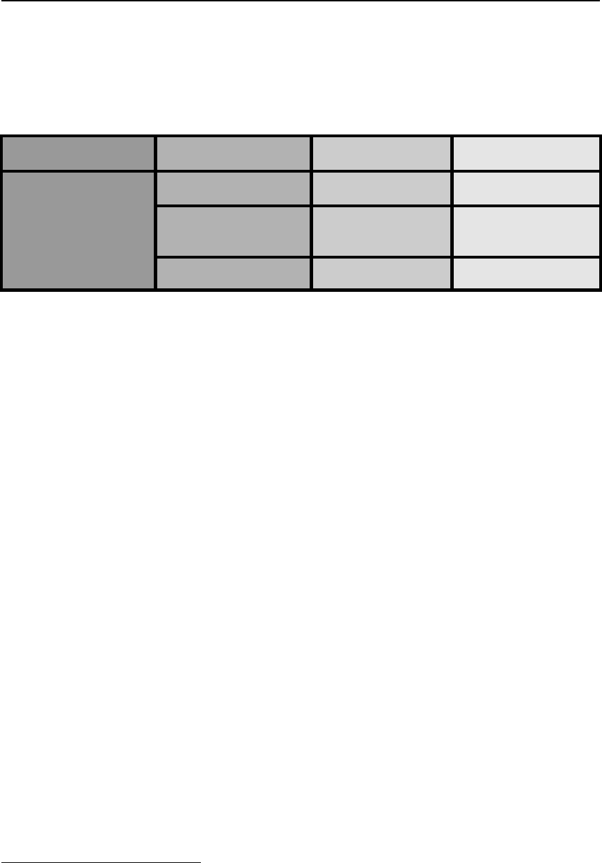
Table 1. Grounding/Equipotential Bonding Requirements
Technical
Requirement
Implementing Process
Test Method
Required Limit(s)
Grounding/Bonding
System
Equipment Grounding
Conductor
ANSI/ESD S6.1
< 1.0 ohm
impedance
(4)
Auxiliary Ground
ANSI/ESD S6.1
< 25 ohms to the
Equipment Grounding
Conductor
Equipotential Bonding
ANSI/ESD S6.1
< 1.0 x 10
9
ohms
(5)
8.2 Personnel Grounding
All personnel shall be bonded or electrically connected to the selected grounding/equipotential
bonding system when handling ESDS items. The personnel grounding method(s) shall be selected
from Table 2.
When personnel are seated at ESD protective workstations, they shall be connected to the selected
grounding/equipotential bonding system via a wrist strap system.
For standing operations, personnel shall be grounded via a wrist strap or by a footwear/flooring
system meeting the requirements of Table 2.
When garments are used to achieve personnel grounding, it shall be documented in the ESD
control program plan. It shall also meet the groundable static control garment system resistance
requirements defined in Table 2 and the groundable static control garment in Table 3.
4
If there is a GFCI, this measurement is not required and may cause the GFCI to activate.
5
The maximum resistance between any ESD control items and the common connection point.
ANSI/ESD S20.20-2021
6
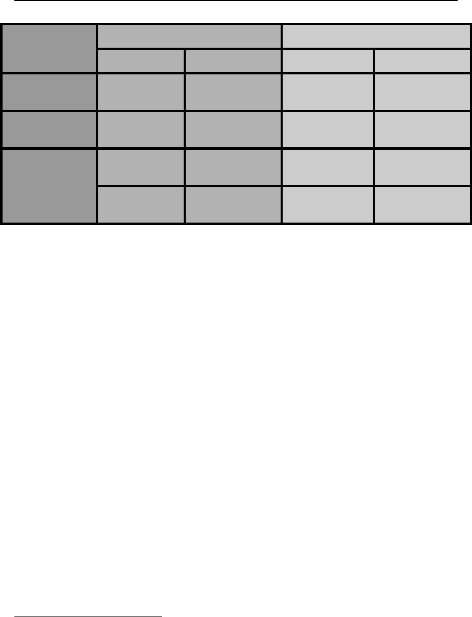
Table 2. Personnel Grounding Requirement
Technical
Requirement
Product Qualification
Compliance Verification
Test Method(s)
Required Limit(s)
Test Method(s)
Required Limit(s)
Wrist Strap
System
ANSI/ESD S1.1
System
Resistance
< 3.5 x 10
7
ohms
ESD TR53
Wrist Strap
Section
System
Resistance
< 3.5 x 10
7
ohms
Groundable Static
Control Garment
System
ANSI/ESD
STM2.1
System
Resistance
< 3.5 x 10
7
ohms
ESD TR53
Garment
Section
System
Resistance
< 3.5 x 10
7
ohms
Footwear/Flooring
System –
(Both limits shall
be met)
6
ANSI/ESD
STM97.1
System
Resistance
< 1.0 x 10
9
ohms
ESD TR53
Footwear Section
System
Resistance
< 1.0 x 10
9
ohms
(7)
ANSI/ESD
STM97.2
Peak Voltage
< 100 volts
ESD TR53
Flooring Section
Point to Ground
Resistance
< 1.0 x 10
9
ohms
(7)
8.3 ESD Protected Areas (EPAs)
Handling of ESDS items, parts, assemblies, and equipment without ESD protective coverings or
packaging shall be performed in an EPA. The EPA shall have clearly identified boundaries.
An EPA can consist of a single workstation, entire room, building, or other designated areas.
Access to the EPA shall be limited to personnel who have completed appropriate ESD training or
be escorted by trained personnel while in an EPA.
An EPA shall be established wherever ESDS items are handled. However, there are many ways
to establish ESD controls within an EPA. Table 3 lists optional ESD control items which can be
used to control static electricity. The required limits and test methods for ESD control items selected
for use in the ESD control program become mandatory.
8.3.1 Insulators
The Organization's ESD control program shall include a plan for handling insulators to mitigate field
induced CDM damage. All nonessential insulators shall be separated from any ESDS item by at
least 300 mm. Areas can be designated within the EPA to store static generating items provided
the areas do not cause any of the requirements below to be exceeded. When qualifying a process
to be deployed in an EPA, process essential insulators shall be evaluated in accordance with how
the insulators will be used.
For initial process qualification and ongoing compliance verification measurements, one of the
following criteria shall be met:
• Measure the field at the location where the ESDS item is handled. The electrostatic field shall
be less than 5000 volts/meter (125 volts/inch).
or
• For any process essential insulators located less than or equal to 25 mm from an unprotected
ESDS item, the voltage on the surface of the insulator shall be less than 125 volts when
measured with a non-contact electrostatic voltmeter. When using an electrostatic field meter,
6
A periodic body voltage generation test should be done to verify the voltage is less than 100 volts.
7
The required limit of < 1.0 x 10
9
ohm is the "maximum" allowed value. The user should document the
resistance values that were measured for product qualification for the footwear and the flooring system to
comply with the < 100 volts body voltage generation and use these resistances for compliance verification.

ANSI/ESD S20.20-2021
7
the reading shall be less than 125 volts when measured at the meter's stipulated measuring
distance.
• For any process essential insulators located more than 25 mm, but less than 300 mm from an
unprotected ESDS item, the voltage on the surface of the insulator shall be less than 2000 volts
when measured with a non-contact electrostatic voltmeter. When using an electrostatic field
meter, the reading shall be less than 2000 volts when measured at the meter's stipulated
measuring distance.
NOTE: Insulators should be measured after normal handling that could occur during the processing of ESDS
items with materials in use in the EPA. The insulators should not be artificially charged. See ESD TR20.20 for
more information.
NOTE: See ESD TR20.20 for more information on insulators and charge mitigation techniques.
NOTE: The accurate measurement of electrostatic fields requires that the person making the measurement
is familiar with the operation of the measuring equipment. An electrostatic field meter responds to the
electrostatic field emanating from a charged surface and converts the field into a voltage when the meter is
positioned at the meter's stipulated distance. When measuring relatively large conductors, the electrostatic
field meter reading is the actual voltage on the conductor when measured at the meter's stipulated measuring
distance. However, for non-uniformly charged insulators, the voltage indicated by the field meter (when
measured at the meter's stipulated measuring distance) is an average of the electrostatic field strengths of the
charged insulator.
NOTE: If a non-contact electrostatic voltmeter is used, care must be taken to ensure the non-contact
electrostatic voltmeter's spot resolution (the smallest measurement area that the meter can resolve) is smaller
than the insulator being measured. For a non-contact electrostatic voltmeter, this is a combination of aperture
size and distance to the object. It is recommended to measure the item at the smallest distance stated by the
manufacturer.
8.3.2 Isolated Conductors
If a conductor that cannot be grounded or equipotentially bonded comes into contact with an ESDS
item, the process shall ensure that the potential between the isolated conductor and ground is
between -35 volts and +35 volts.
For an isolated conductor that does not come into contact with an ESDS item, the requirements for
insulators in Section 8.3.1 shall be met.
NOTE: For accurate measurements, it is recommended to use a high impedance contact voltmeter. If a non-
contact electrostatic voltmeter or electrostatic field meter is used, care must be taken to ensure the spot
resolution (the smallest measurement area that the meter can resolve) is smaller than the isolated conductor
being measured. For a non-contact electrostatic voltmeter, this is a combination of aperture size and distance
to the object. It is recommended to measure the item at the smallest distance stated by the manufacturer.