X service技术参数.pdf - 第24页
24 PCB Conveyor SIPLACE PCB Barcode for Product-Controlled Production (Option) Label dimensions S troke width (W): 0.19 < W ≤ 0.3 mm (correspon ds to high and medium den- sity), stroke len gth: ≥ 4 mm, l ength of the …
23
PCB Conveyor
Flexible Dual Conveyor
Technical Data for the Dual Conveyor
Fixed conveyor side Right or left
PCB format
Standard (length x width)
Wide board mode
Long board option
Long board option in Wide board mode
Dual conveyor in Single conveyor mode
Standard
Wide board mode
Long board option
Long board option in Wide board mode
50 x 50 mm² to 450 x 216 mm²
50 x 50 mm² to 450 x 250 mm²
50 x 80 mm² to 610 x 216 mm²
50 x 80 mm² to 610 x 250 mm²
50 x 50 mm² to 450 x 380 mm²
50 x 50 mm² to 450 x 450 mm²
50 x 80 mm² to 610 x 380 mm²
50 x 80 mm² to 610 x 450 mm²
PCB thickness
Standard 0.3 mm to 4.5 mm (± 0.2 mm)
(thicker PCBs on request)
Max. PCB warpage Up: 6 mm - PCB thickness
Down: 0.3 mm + PCB thickness
PCB weight max. 3 kg
Clearance on PCB underside
Standard
Option
25 mm ± 0.2 mm
max. 40 mm ± 0.2 mm
PCB transport height 830mm ± 15mm (standard)
900mm ± 15mm (optional)
930mm ± 15mm (optional)
950mm ± 15mm (SMEMA: optional)
Type of interface SMEMA / SIEMENS
Component-free PCB handling edge 3 mm
PCB changeover time < 2.5 s
PCB positioning accuracy ± 0.5 mm
Conveyor mode synchronous or asynchronous
Components on each conveyor same or different
PCB width on each conveyor same or different
Ink spot recognition synchronous: not possible,
asynchronous: possible
Automatic width adjustment synchronous: possible, asynchronous: possible
24
PCB Conveyor
SIPLACE PCB Barcode for Product-Controlled
Production (Option)
Label dimensions Stroke width (W): 0.19 < W ≤ 0.3 mm (corresponds to high and medium den-
sity), stroke length: ≥ 4 mm, length of the barcode template window: ≤ 90 mm
Recommended label
colors
Coding: black, dark green, dark blue, background: white, beige, yellow, orange
(contrast ratio > 70% to DIN 66236
Code types Code 39, Code 128 / EAN 128, Codabar, 2/5 IATA 2/5 industrial, 2/5 interleaved,
UPC, EAN, Pharma Code, EAN Addendum (others available on request),
max. 25 digits, a barcode filter may be defined
Laser scanner safety Laser diode 670 nm (red) / 1.2 mW
Laser protection class 2, degree of protection IP65
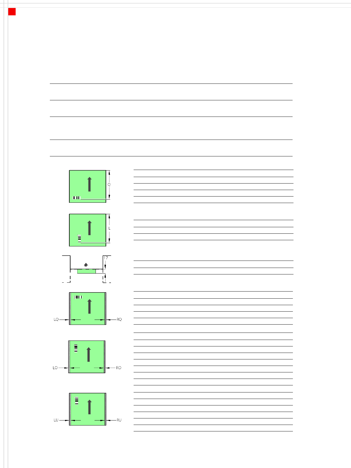
PCB barcode reader Q [mm]
2D on top 390
1D on top 390
2D on bottom 430
1D on bottom 430
PCB barcode reader L [mm]
1D on top 320 - 350
1D on bottom 380 - 410
PCB barcode reader PCB rear projection [mm]
2D on bottom (dual conveyor) 17
PCB barcode reader LQ [mm] RQ [mm]
2D on top 3 3
1D on top 3 3
2D on bottom 5 5
1D on bottom 5 5
PCB dimensions/conveyor LO [mm] RO [mm]
460 mm SC 3 20
508 mm SC 3 44
216 mm DC1 3 24
250 mm DC1, 450 mm SM1 3 58
216 mm DC2 3 3
250 mm DC2, 450 mm SM2 3 3
PCB dimensions/conveyor LU [mm] RU [mm]
460 mm SC 20 3
508 mm SC 44 3
216 mm DC1 3 3
250 mm DC1, 450 mm SM1 3 3
216 mm DC2 24 3
250 mm DC2, 450 mm SM2 58 3
SC - Single conveyor, DC1/2 - Dual conveyor, track 1/2, SM1/2 - Dual conveyor in Single conveyor mode, track 1/2
Downstream
machine
Upstream
machine
PCB
PCB barcode scanner 1D on top
PCB barcode scanner 1D on bottom
25
Location 1
Location 3
Location 2
Location 4
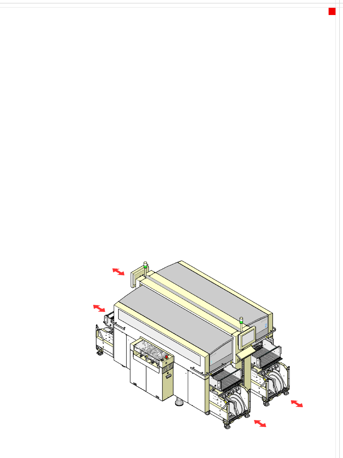
Component Feeding
SIPLACE X-Series Component
Changeover Table
Description
The component changeover
tables are stand-alone mod-
ules that can be set up at an
external set-up area with
feeder modules. Up to four
component changeover
tables may be docked in the
machine. A component
changeover table can be
replaced with just a short
interruption of the produc-
tion process. The chassis runs
smoothly and is easy to
maneuver.
The component table has a
capacity of up to 40 locations
for 8 mm X tape feeder mod-
ules. The total capacity with
four component changeover
tables is thus 160 x 8 mm
tracks.
Dummy feeder modules are
used at unassigned locations
to protect the operators.
The component feeders are
at rest during the placement
process - allowing tapes to be
spliced without stopping the
machine.
An optional component bar-
code reader can be used to
scan and check the barcodes
on the tape reels, thus guar-
anteeing that the compo-
nents are allocated to the
correct tracks (traceability).
Component changeover
tables from the SIPLACE HF-
series can also be used.
This means that you can con-
tinue to use the S-series tape
feeder modules and all other
feeder modules from the
same generation, such as
vibratory stick feeders, bulk-
case feeders, Dip modules,
component disposal modules
and surftape feeder modules.
Please note, however, that
the appropriate docking unit
will have to be fitted for com-
ponent changeover tables
from the SIPLACE HF-series.
The SIPLACE HF-series com-
ponent changeover table
cannot be used with the
20-nozzle Collect & Place
head.