X service技术参数.pdf - 第31页
31 Component Feeding Manual Trays Manual tra y Compon ent feeder table Waffle t ray Technical data Ma nua l tray - pos si ble po si tions Sizes 136 x 360 mm²; requires 5 locations 260 x 360 mm²; requires 9 locations Max.…
30
Component Feeding
Dummy Feeder Modules
Dummy feeder modules for component changeover tables
from the SIPLACE X-series
The dummy feeder module for the SIPLACE X-series fills one
track on the component changeover table.
Dummy feeder modules for component changeover tables
from the SIPLACE HF-series
The following dummy feeder module variants are available for
component changeover tables from the SIPLACE HF-series:
SIPLACE dummy feeder module for 1 location
SIPLACE dummy feeder module for 6 - 10 locations
SIPLACE dummy feeder module for 11 - 20 locations
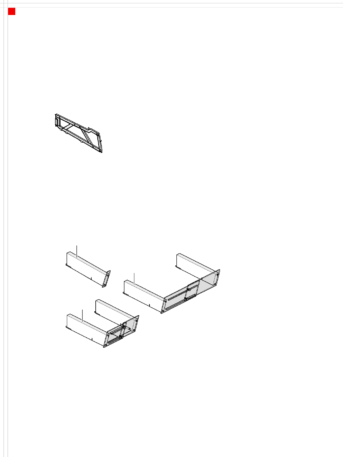
Dummy feeder module for one track
Dummy feeder module for 1 location
Dummy feeder module for
6 - 10 locations
Dummy feeder module for
11 - 20 locations
Danger
To ensure that your SIPLACE
placement machine runs
safely, a feeder must be
assigned to every location on
the component changeover
table. If you do not have
enough feeder modules,
then you should use dummy
feeder modules as space
holders.
31
Component Feeding
Manual Trays
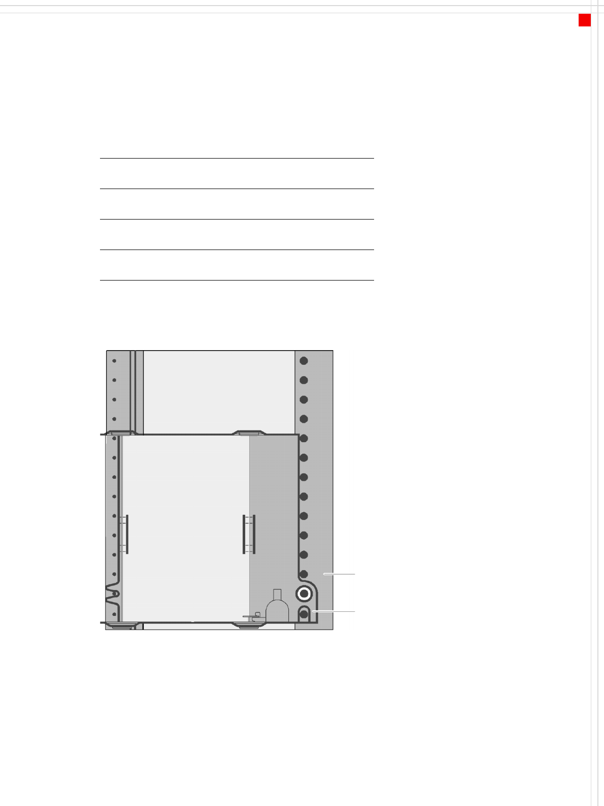
Manual tray
Component feeder table
Waffle tray
Technical data
Manual tray - possible positions
Sizes 136 x 360 mm²; requires 5 locations
260 x 360 mm²; requires 9 locations
Max. tray
height
12.5 mm, including component
Parts Waffle tray carrier
Tray holder
JEDEC waffle
tray
Directly in the waffle tray carrier
136 mm wide
Description
The manual tray is a device
for holding JEDEC trays used
to supply components. The
waffle trays are changed
manually. The manual tray is
placed on the component
feeder table just like a feeder
module. There are two differ-
ent versions of the waffle-
pack tray: one fills 5 locations
and the other 9 locations on
the component table.
The manual tray is fitted at
locations 2 and 4 on X2
machines, but just at location
3 on X3 machines. If a nozzle
changer is installed at loca-
tion 2, a manual tray cannot
be used.
The manual tray can only be
used on component change-
over tables from the SIPLACE
HF-series.
The manual tray set-up is
recommended if there are
just a few component types
to be placed from a tray.
32
Component Feeding
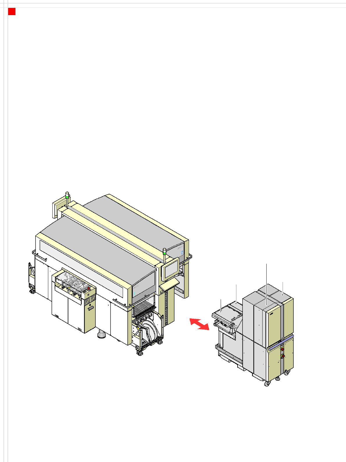
Matrix Tray Changer
Description
For numerous tray fed com-
ponents we recommend an
automatic tray change using
a matrix tray changer (MTC).
The MTC set-up is precisely
matched to the placement
sequence in order to opti-
mize the timings and dis-
tances traveled.
Two bins with component
trays move independently of
one another in the vertical di-
rection until the desired mag-
azine is within the range of
the feed axis. The horizontal
feed axis transports the tray
from the bin to within the
range of the placement head.
The first magazine is made
available as soon as a PCB
moves onto the PCB convey-
or, and valid panel and set-up
data is available. All other
magazine changes are car-
ried out time-neutrally dur-
ing the placement process.
The magazines can be refilled
without stopping the
machine. Defective compo-
nents are returned to the
original tray.
The matrix tray changer can-
not be used with the 20-
nozzle Collect & Place head.
Tray supply 2
Tray supply 1
Feed
axis 1
Feed
axis 2