X service技术参数.pdf - 第26页
26 Comp onent Fee ding Compon ent Chan geover Table Technical Data *) Not togeth er with the 20-nozzle Colle ct & Place head SIPL ACE X-series component change over t abl e SIPL ACE HF-series component changeo ver ta…
25
Location 1
Location 3
Location 2
Location 4
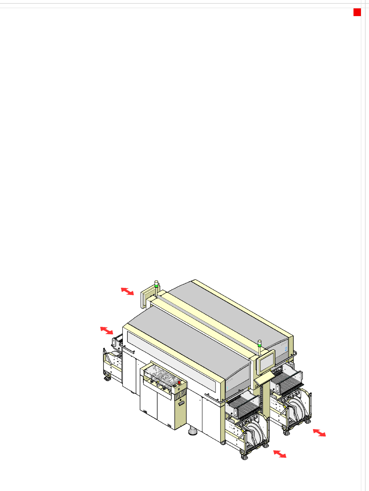
Component Feeding
SIPLACE X-Series Component
Changeover Table
Description
The component changeover
tables are stand-alone mod-
ules that can be set up at an
external set-up area with
feeder modules. Up to four
component changeover
tables may be docked in the
machine. A component
changeover table can be
replaced with just a short
interruption of the produc-
tion process. The chassis runs
smoothly and is easy to
maneuver.
The component table has a
capacity of up to 40 locations
for 8 mm X tape feeder mod-
ules. The total capacity with
four component changeover
tables is thus 160 x 8 mm
tracks.
Dummy feeder modules are
used at unassigned locations
to protect the operators.
The component feeders are
at rest during the placement
process - allowing tapes to be
spliced without stopping the
machine.
An optional component bar-
code reader can be used to
scan and check the barcodes
on the tape reels, thus guar-
anteeing that the compo-
nents are allocated to the
correct tracks (traceability).
Component changeover
tables from the SIPLACE HF-
series can also be used.
This means that you can con-
tinue to use the S-series tape
feeder modules and all other
feeder modules from the
same generation, such as
vibratory stick feeders, bulk-
case feeders, Dip modules,
component disposal modules
and surftape feeder modules.
Please note, however, that
the appropriate docking unit
will have to be fitted for com-
ponent changeover tables
from the SIPLACE HF-series.
The SIPLACE HF-series com-
ponent changeover table
cannot be used with the
20-nozzle Collect & Place
head.
26
Component Feeding
Component Changeover Table
Technical Data
*) Not together with the 20-nozzle Collect & Place head
SIPLACE X-series component
changeover table
SIPLACE HF-series component
changeover table*
)
Length x width 752 x 592 mm²
Height for
830 mm PCB conveyor height
900 mm PCB conveyor height
930 mm PCB conveyor height
950 mm PCB conveyor height
820 mm
890 mm
920 mm
940 mm
830 mm
900 mm
930 mm
950 mm
PCB transport height 830 mm ± 15 mm (standard)
900 mm ± 15 mm (SMEMA)
930 mm ± 15 mm (SMEMA)
950 mm ± 15 mm (SMEMA)
830 mm ± 15 mm (standard)
900 mm ± 15 mm (SMEMA)
930 mm ± 15 mm (SMEMA)
950 mm ± 15 mm (SMEMA)
Weight
without feeder modules
with feeder module at all locations
80.4 kg
approx. 139.6 kg
88.9 kg
143.7 kg
Reel diameter
standard
maximum
up to 432 mm (17“)
483 mm (19“)
up to 432 mm (17“)
483 mm (19“)
Locations for feeder modules max. 40 max. 15
Changeover time less than 1 min. less than 1 min.
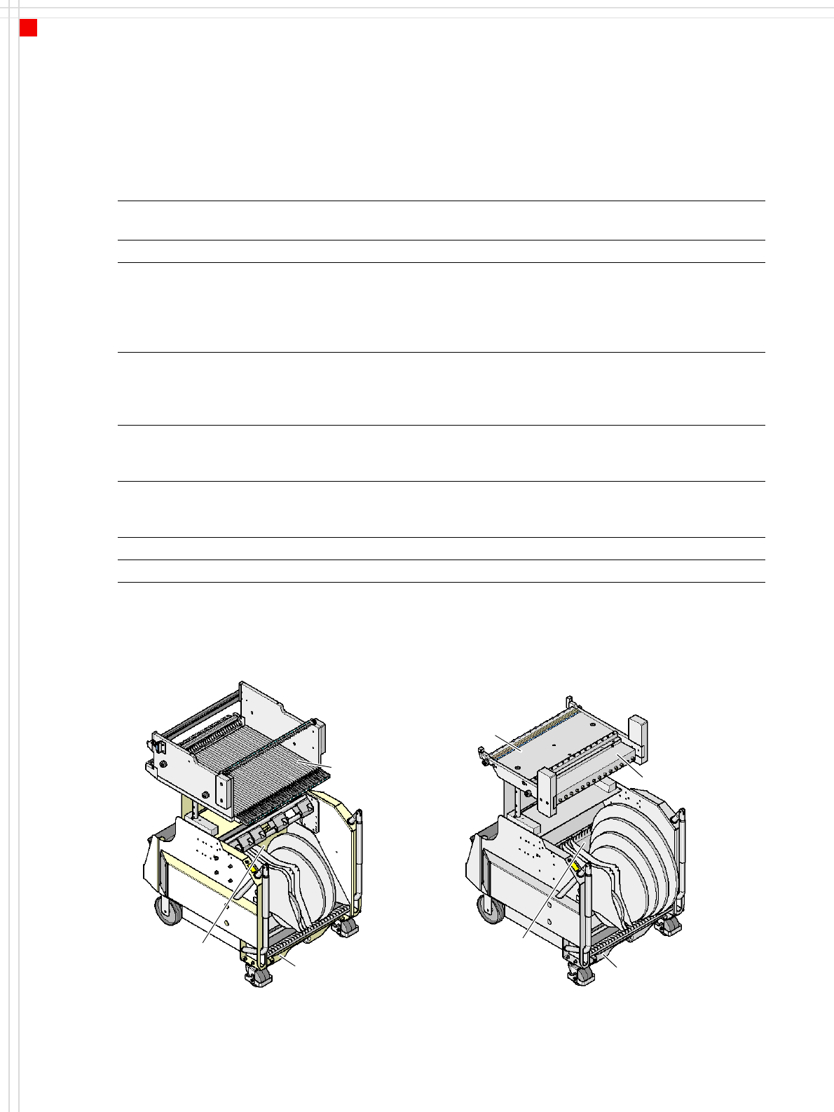
Communication unit
Waste container
for pieces of used tape
Component
feeder table
Tape container
SIPLACE X-series component changeover table SIPLACE HF-series component changeover table
Waste container
for pieces of used tape
Component
feeder table
Tape container
27
Component Feeding
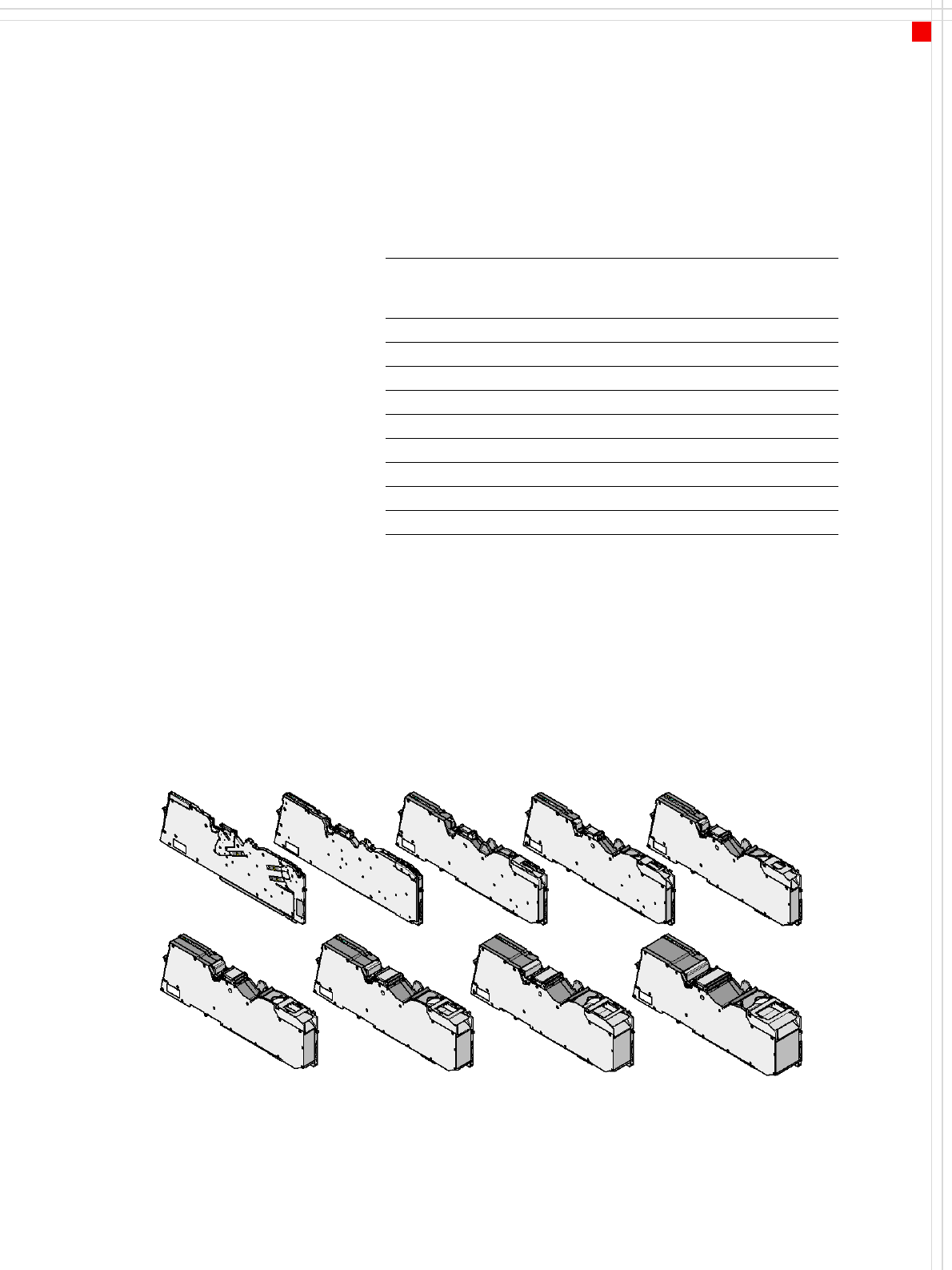
Tape Feeder Modules, X-Series
Description
The single-track tape feeder
modules for the X-series pro-
cess paper and blister tapes
from 8 to 88 mm wide.
Component tapes with a per-
manently adhesive cover foil
(PSA foil) can be processed
with the PSA kit option.
The transport increment can
be varied over a wide range.
The foil tear-off force can be
set manually on all the feeder
modules.
The X feeder modules are
characterized by their excel-
lent accuracy of the pick-up
position, online and offline
programmability of the
feeder modules and easy
handling that allows the
feeder modules to be quickly
changed during the place-
ment process.
The multicolor status display
signals the operating status-
es: green for "Standby“, or-
ange for "Warning“ and red
for "Error“. Information ap-
pears on the LCD display for
"orange“ and "red“.
The EDIF unit (energy and
data interface) powers the
feeder module without con-
tact. Communication with
the placement machine also
takes place via this interface.
Technical data
*) In 4 mm increments
Model LxH
[mm²]
Width
[mm]
Loca-
tion
Transpor t
increment
[mm]
Max. tape
height
[mm]
8 mm X 587x200 10.8 1 1/2/4/8 3.5
12 mm X 587x200 22.6 2 4 - 16 *) 6.5
16 mm X 587x200 34.4 3 4 - 20 *) 25
24 mm X 587x200 34.4 3 4 - 32 *) 25
32 mm X 587x200 46.2 4 4 - 40 *) 25
44 mm X 587x200 58.0 5 4 - 52 *) 25
56 mm X 587x200 69.8 6 4 - 64 *) 25
72 mm X 587x200 81.6 7 4 - 80 *) 25
88 mm X 587x200 105.2 9 4 - 96 *) 25
8 mm X
12 mm X
16 mm X 24 mm X 32 mm X
44 mm X 56 mm X 72 mm X 88 mm X