00191921-01.pdf - 第38页
38 SIPLACE 8 0F 4 - Genera l Vie w The descrip tion of the us er interface, t he safety fun ctions and the menus relating to the SIPLACE 80S-20 also g enerally appl y to the 80F 4 auto- matic place ment machine s. As an …

37
● Open the horizontal tensioners (item 11)
● Pull the two actuating tubes (item 6) towards you at the same time and lift
up the bracket (item 7) to lock the raised component table bed in its top
end position.
● Hold down the button (item 5) for raising the component table bed (item 4)
until the component table bed reaches its top end position.
● Unplug the component table power cable (item 2).
● Unplug the component table control cable (item 1).
● Disconnect the compressed air supply (item 3).
● Remove the component table.
Docking the component table
WARNING
Check that the placement head is outside the range of the component
table.
CAUTION
When docking the component table, ensure that the table bed is in its top
end position and the bracket (item 7) is folded up.
● Cut off the empty tapes for the feeder modules.
● Make sure that the contact surface (item 10) for the component table bed
is clean.
● CAREFULLY push the component table into the placement system.
● Connect the compressed air supply (item 3).
● Plug in the control cable (item 1).
● Plug in the power cable (item 2) for the component table.
● Pull the two actuating tubes (item 6) towards you at the same time and
then lower the bracket (item 7) in order to be able to lower the component
table bed.
● Check that the centEring holes in the component table bed lie precisely
over the centering pins of the placement system.
● Hold down the button (item 5) until the component table bed reaches its
top end position.
● Release the button and the component table bed will descend.
● Ensure that the centring pins engage in the centring holes in the compo-
nent table bed and that the component table bed is fully lowered.
● Fold up the bracket (item 7) of the component table.
● Lock the two horizontal tensioners (item 11).
● Close the side screens and protective cover.
● Press the Start button to start the placement system.
38
SIPLACE 80F
4
- General View
The description of the user interface, the safety functions and the menus
relating to the SIPLACE 80S-20 also generally apply to the 80F
4
auto-
matic placement machines.
As an option a wafflepack changer can also be installed in the SIPLACE
80F
4
placement machine. Since the F
4
machine only has one gantry
system and has an IC head instead of the second revolver placement
head, operator guidance will differ in some respects from that of the S-20
machine.
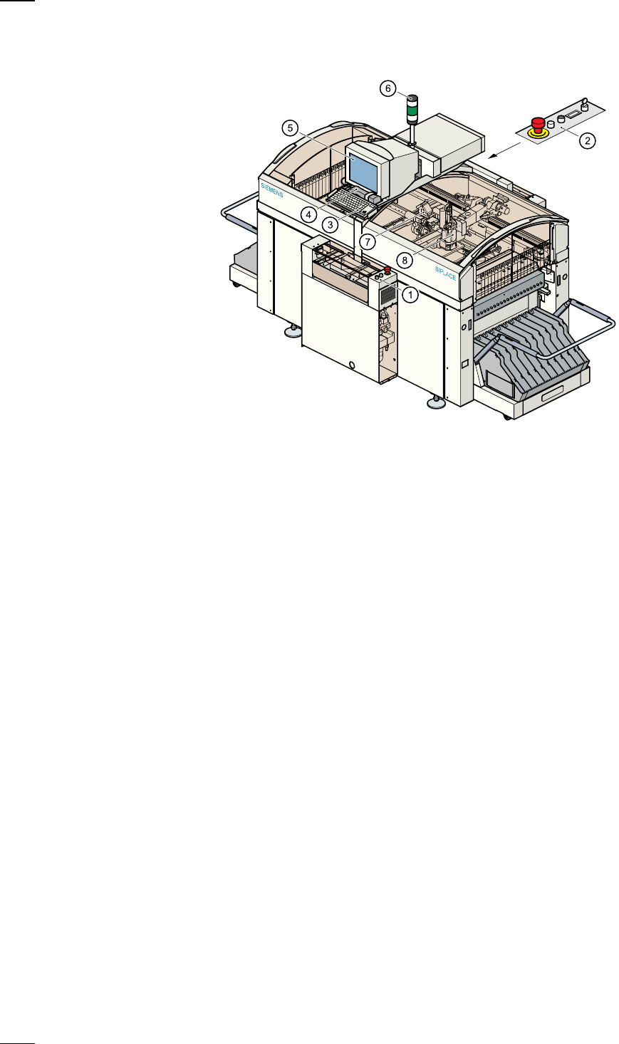
a
Controls, input side
s
Controls, output side
d
Keyboard with integral trackball
f
Component barcode reader
g
Touchscreen
h
Main fault indicator
j
12-segment revolver head
k
IC head
39
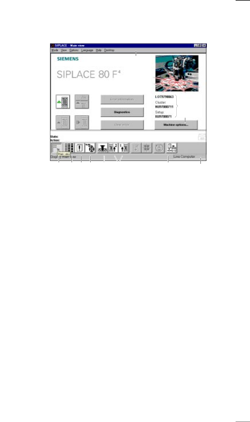
Operator Guidance
’SIPLACE 80F
4
- Main view‘ menu (User level: ’operator’)
a
-
f
Buttons for machine control
a
Process
s
Stop processing
d
Continue processing
f
Abort processing
g
Error information
If an error occurs, you can obtain more details concerning the error in this
submenu.
h
Diagnostics
If an error occurs while a board is being processed, you can start this
diagnostics program in order to analyze and correct the error (option).
j
Clear error
Click on this button and the error message will be removed from the
screen. For reference purposes the error will continue to be held in the
errors list.
k
This displays the file name of the job, the cluster that was loaded and the
set-up.
l
-
H
Buttons and icons for calling menus for machine control
l
Machine options
;
Display main view
A
Display setup and component verification with barcode
S
Display errors
D
PCB feeders
F
SF Gantry 1
G
SF PCB transport 1 and SF PCB transport 2 (you cannot access the SF
PCB transport 2 menu unless the twin conveyor option has been
installed.)
H
GEM status, placement program and terminal service (option)
J
Display of the machine‘s operating mode: line computer, GEM host,
stand-alone
K Menu line with pull-down menus
Via these pull-down menus you also have access to all of those functions
and options which you require for controlling the machine.
;ASDF G H
a
df
g
h
j
s
k
l
K
J
↑ UM 3.3