00191921-01.pdf - 第40页
40 ’Single functions Gantry 1’ menu ↑ UM 5.2 In addition to th e Revolver head f unctions the S ingle function s Gantry 1 menu also contains functions for the IC he ad. These sub menus includ e: – Gantry fun ctions (see …
39
Operator Guidance
’SIPLACE 80F
4
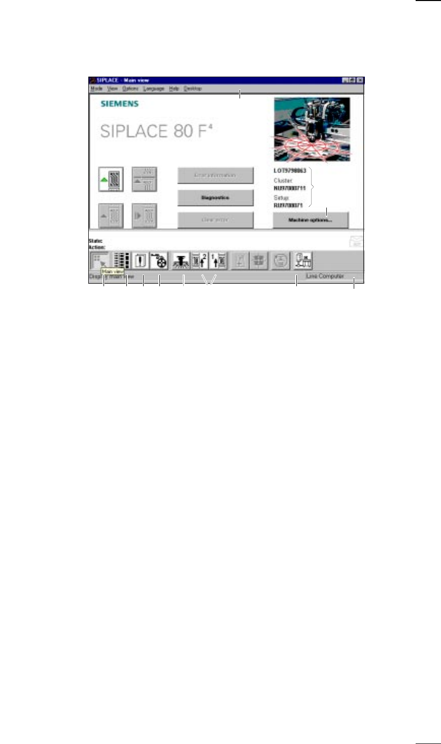
- Main view‘ menu (User level: ’operator’)
a
-
f
Buttons for machine control
a
Process
s
Stop processing
d
Continue processing
f
Abort processing
g
Error information
If an error occurs, you can obtain more details concerning the error in this
submenu.
h
Diagnostics
If an error occurs while a board is being processed, you can start this
diagnostics program in order to analyze and correct the error (option).
j
Clear error
Click on this button and the error message will be removed from the
screen. For reference purposes the error will continue to be held in the
errors list.
k
This displays the file name of the job, the cluster that was loaded and the
set-up.
l
-
H
Buttons and icons for calling menus for machine control
l
Machine options
;
Display main view
A
Display setup and component verification with barcode
S
Display errors
D
PCB feeders
F
SF Gantry 1
G
SF PCB transport 1 and SF PCB transport 2 (you cannot access the SF
PCB transport 2 menu unless the twin conveyor option has been
installed.)
H
GEM status, placement program and terminal service (option)
J
Display of the machine‘s operating mode: line computer, GEM host,
stand-alone
K Menu line with pull-down menus
Via these pull-down menus you also have access to all of those functions
and options which you require for controlling the machine.
;ASDF G H
a
df
g
h
j
s
k
l
K
J
↑ UM 3.3
40
’Single functions Gantry 1’ menu
↑ UM 5.2 In addition to the Revolver head functions the Single functions Gantry 1
menu also contains functions for the IC head. These submenus include:
– Gantry functions (see the ’Gantry functions’ menu on page 25).
– Revolver head functions (see ’Revolver head functions’ menu on
page 26).
– IC head functions
– Vacuum test revolver head (see ’Vacuum test revolver head’ menu on
page 27).
– Nozzle offset revolver head (see ’Nozzle offset revolver head’ menu on
page 27).
– Nozzle configuration revolver head (see ’Nozzle configuration revolver
head’ menu on page 28).
– Nozzle-changer configuration revolver head (see ’Nozzle-changer config-
uration revolver head’ menu on page 29).
– Nozzle-changer configuration IC head
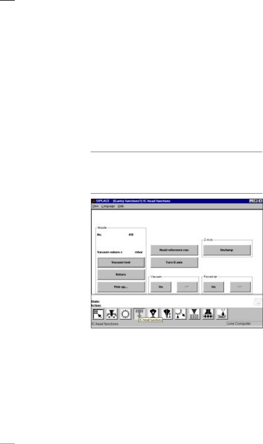
’IC head functions’ menu
↑ UM 5.2.2 This menu is used for checking the IC head functions.
NOTE
If protective covers on the machine are open, you will need to unlock the
key-operated switch before you can execute functions.
The cover has to be closed before the axes can move.
When you quit the IC head functions menu, the IC head and the revolver
head will carry out a reference run over the rejects box.
Vacuum test The vacuum value and the height of the nozzle are measured and dis-
played on the screen.
Return The nozzle is returned to the nozzle changer.
Pick up... With this function you can change the nozzles configured in the nozzle
changer setup.
● Click on the button and enter the number of the desired nozzle into the
dialog box which opens. If there is already a nozzle in the IC head, it will
be returned first.
Head reference run The z and d axes perform a head reference run.
Turn D-axis You can turn the d axis for testing purposes.
41
Unclamp Z axis When you press this button an information box with the following
message is displayed on the screen:
Z axis clamping is open!
Close clamp?
OK
● When you click on OK the z axis will be clamped.
Vacuum on/off The vacuum will be switched on or off.
Forced air on/off The forced air will be switched on or off.
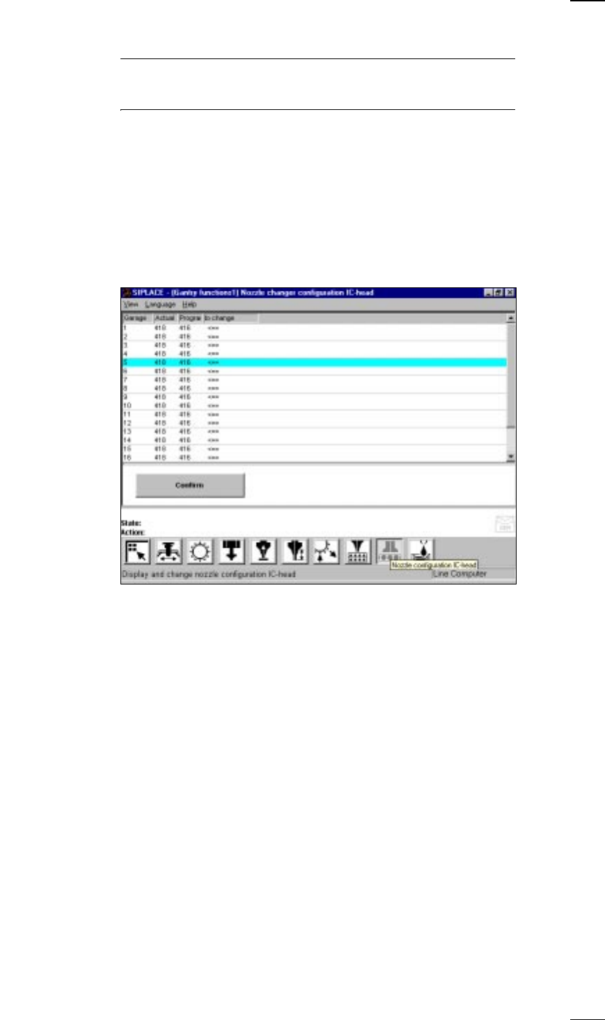
’Nozzle-changer configuration IC-head’ menu
↑ UM 5.2.9 This menu is used for
– Accessing nozzle types
– Check nozzles in the IC head and
– Changing nozzles in the IC head
Program Setup specified in the line computer
To change The arrow indicates that the nozzle has to be changed.
Actual Current value at the nozzle changer
Confirm • Change the nozzle in the corresponding nozzle garage.
• Mark the corresponding nozzle with the cyan bar in the list field.
• Click on the Confirm button.
The programmed and actual values have to be identical.
In this way you can define up to 20 nozzles which will need to be
confirmed individually.