0771445_7708_Mar2018_077144500.pdf - 第21页
Model 7708 M ultiplexer M odule Instructions for use w ith DAQ6510 077144500 / April 2018 21 Verify ing temperature Thermoc ouple, thermistor, and RT D temperature re adings are derived f rom DC volts and res istance mea…
Model 7708 Multiplexer Module Instructions for use with DAQ6510
20 077144500 / April 2018
Ω Range
Nominal
resistance
Nominal reading limits
(1 year, 18°C to 28°C)
Recalculated limits**
1 Ω*
1 Ω
0.999715 mΩ to
1.000285 Ω
__________ to __________ Ω
10 Ω
10 Ω
9.99895 mΩ to 10.00105 Ω
__________ to __________ Ω
100 Ω*
100 Ω
99.9895 Ω to 100.0105 Ω
__________ to __________ Ω
1 kΩ
1 kΩ
0.999929 Ω to 1.000081 kΩ
__________ to __________ kΩ
10 kΩ
10 kΩ
9.99929 Ω to 10.00081 kΩ
__________ to __________ kΩ
100 kΩ
100 kΩ
99.9905 Ω to 100.0095 kΩ
__________ to __________ kΩ
1 MΩ
1 MΩ
0.999894 Ω to
1.000106 MΩ
__________ to __________ MΩ
10 MΩ
10 MΩ
9.99590 Ω to 10.00410 MΩ
__________ to __________ MΩ
100 MΩ
100 MΩ
99.7970 Ω to 100.2030 MΩ
__________ to __________ MΩ
* Enable offset compensation for the 100 Ω range.
** Calculate limits based on actual calibration resistance values and DAQ6510 one-year
resistance accuracy specifications. See Calculating resistance reading limits (on page 14) for
more information.
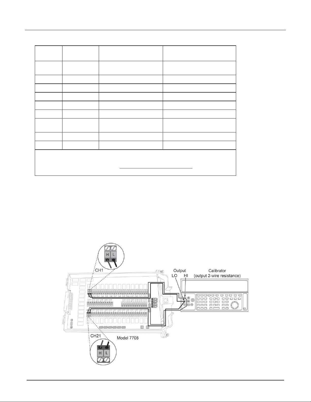
1. Connect the CH1 and CH11 terminals of the module to the calibrator as shown in the next figure.
2. Disable external sense on the calibrator.
3. Set the range of the DAQ6510 to 100 MΩ range.
4. Source a nominal 100 MΩ resistance value. Verify that the reading is within calculated limits for the
100 MΩ range.
5. Return to the CHANNEL swipe screen and open Channel 1.
Model 7708 Multiplexer Module Instructions for use with DAQ6510
077144500 / April 2018 21
Verifying temperature
Thermocouple, thermistor, and RTD temperature readings are derived from DC volts and resistance
measurements, respectively. For that reason, it is not necessary to independently verify the accuracy of
temperature measurements. If the DC volts and resistance functions meet or exceed specifications,
temperature function accuracy is automatically verified.
You can verify temperature accuracy using the following procedures.
Thermocouple temperature
This setup and reading limits table below does not include errors from ice point, thermocouple wire, and
connections. HI and LO connections from the calibrator and 7700 must be electrically isolated from each other.
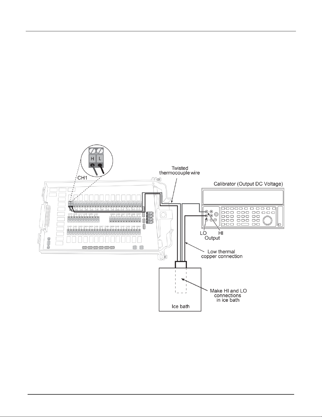
To verify the thermocouple temperature:
1. Connect the DC voltage calibrator output terminals and ice point reference to the CH1 H and L INPUT
terminals of the module using low-thermal shielded connections, as shown in the next figure.
Model 7708 Multiplexer Module Instructions for use with DAQ6510
22 077144500 / April 2018
2. Install the module in Slot 1 of the DAQ6510.
3. Turn on the power.
4. Allow the instrument to warm up for one hour.
5. Make sure that the front-panel TERMINALS switch is set to REAR.
6. On the front panel of the instrument, select the FUNCTION key and then select Temperature.
7. On the Home screen, swipe to the CHANNEL swipe screen.
8. Close channel 101.
9. Set the channel to temperature.
10. Configure the channel for °C units, thermocouple, and internal reference junction as follows:
a. Press the MENU key.
b. Select Channel Settings.
c. Set the Transducer to TC.
d. Set the Thermocouple to K or J.
e. Set the Unit to Celsius.
f. Set the Reference Junction to Internal.
11. Source each of the voltages in the table below based on the type of thermocouple used. Verify that the
temperature readings are within limits.
12. Return to the CHANNEL swipe screen and open Channel 1.
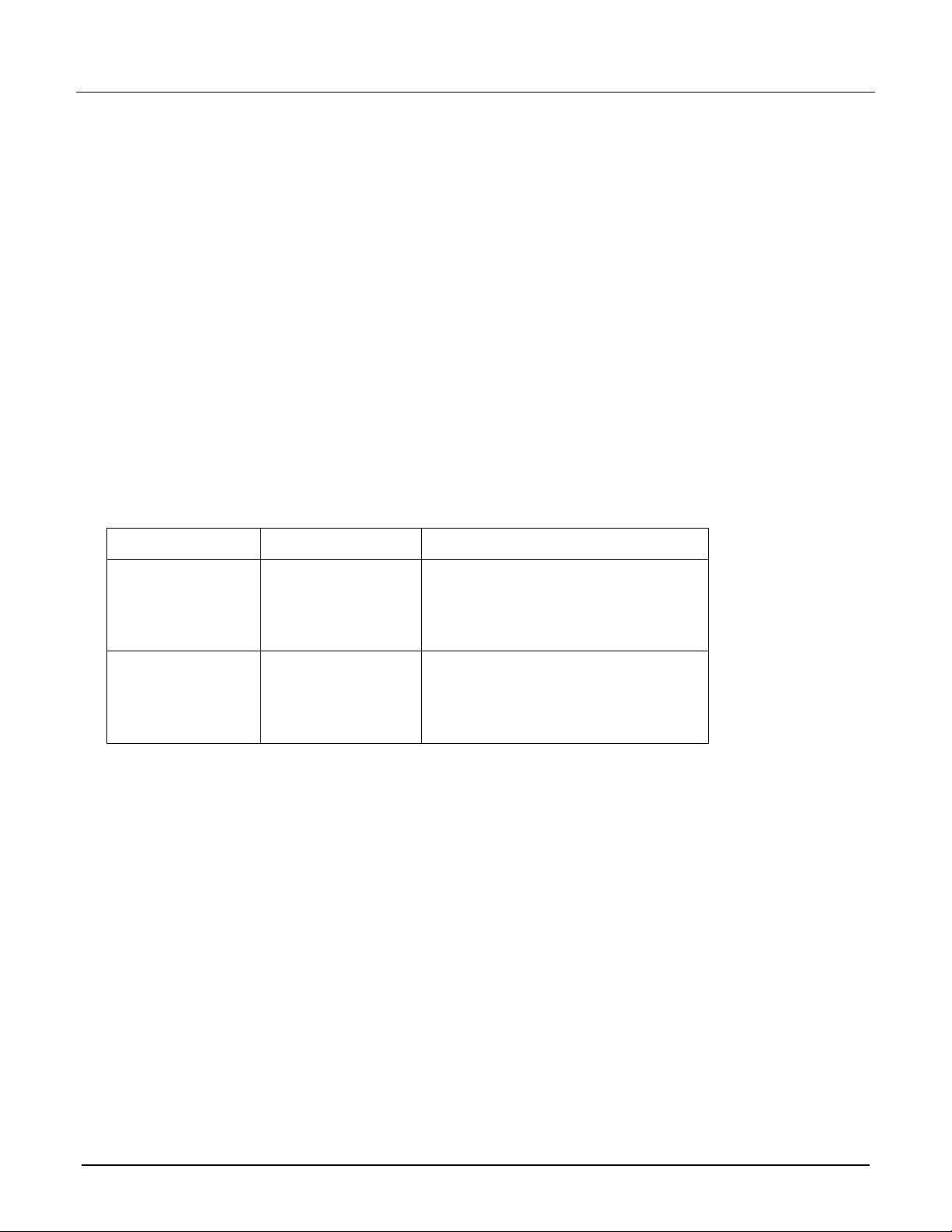
Based on the type of thermocouple used, verify your data against the specifications in the following table.
Thermocouple type
Applied DC voltage*
Reading limits (1 year, 18 °C to 28 °C)
J
-7.659 mV
-192.33 °C to -187.67 °C
0 mV
-1.0 °C to +1.0 °C
42.280 mV
749.0 °C to 751.0 °C
K
-5.730 mV
-192.33 °C to -187.67 °C
0 mV
-1.0 °C to +1.0 °C
54.138 mV
1349.0 °C to 1351.0 °C
*Voltages shown are based on the ITS-90 standard.