0771445_7708_Mar2018_077144500.pdf - 第25页
Model 7708 M ultiplexer M odule Instructions for use w ith DAQ6510 077144500 / April 2018 25 Verifying ratio and av erage Follow the procedure be low to verif y ratio and average. Do not exceed 300 VDC betw een plug -in …
Model 7708 Multiplexer Module Instructions for use with DAQ6510
24 077144500 / April 2018
Verifying frequency
To verify the module frequency:
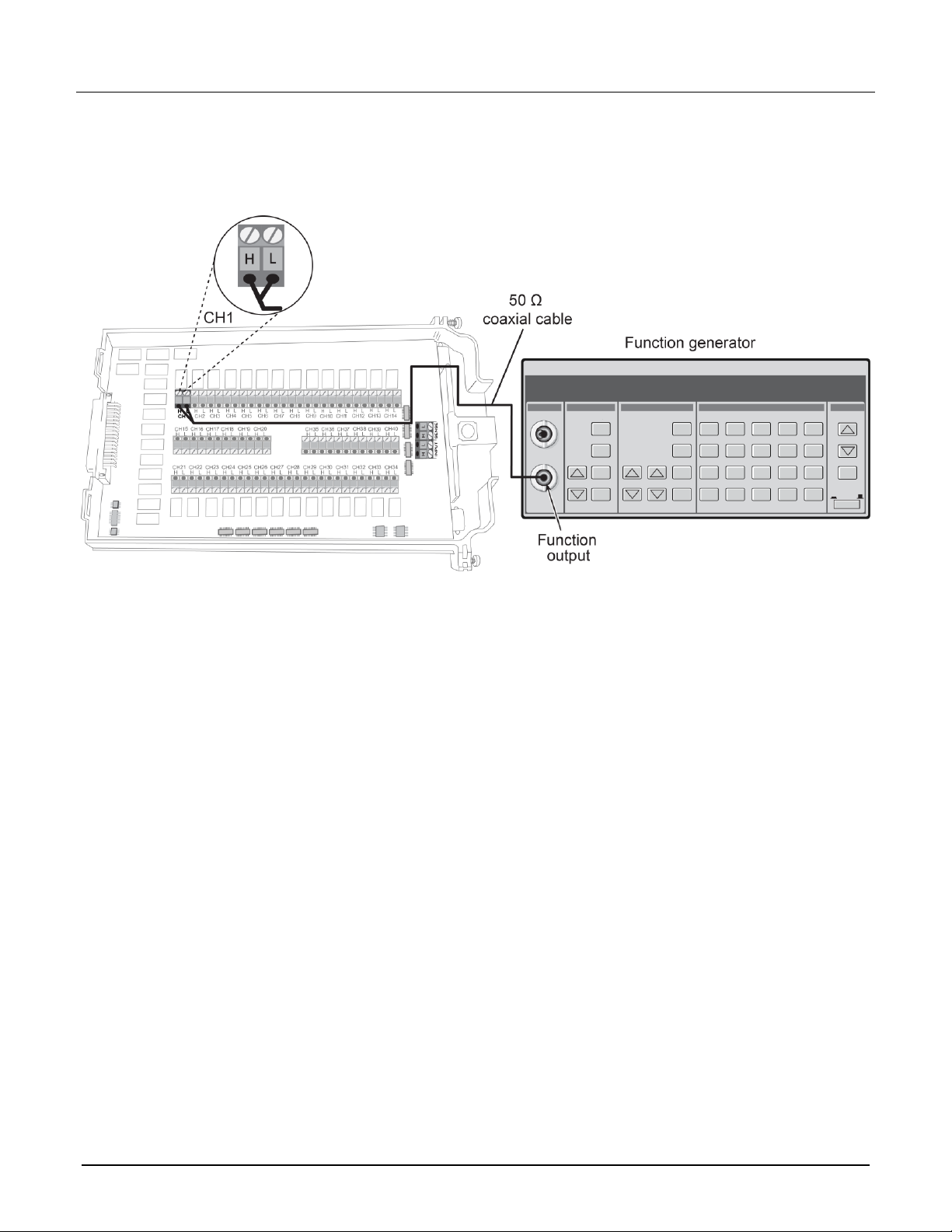
1. Connect the function generator to the CH1 H and L INPUT terminals of the module. Refer to the next figure
for more information.
2. Install the module in Slot 1 of the DAQ6510.
3. Turn on the power.
4. Allow the instrument to warm up for one hour.
5. Make sure that the front-panel TERMINALS switch is set to REAR.
6. Set the function generator to output a 1 kHz 1 V
RMS
sine wave.
7. On the front panel of the instrument, select the FUNCTION key and then select Frequency.
8. On the Home screen, swipe to the CHANNEL swipe screen.
9. Close channel 101.
10. Verify that the DAQ6510 frequency reading is between 0.9999 kHz and 1.0001 kHz.
Model 7708 Multiplexer Module Instructions for use with DAQ6510
077144500 / April 2018 25
Verifying ratio and average
Follow the procedure below to verify ratio and average.
Do not exceed 300 VDC between plug-in module INPUT H and L terminals or between any
adjacent channels. Failure to observe this precaution can cause instrument damage.
Use shielded cables to minimize noise.
To verify ratio and average:
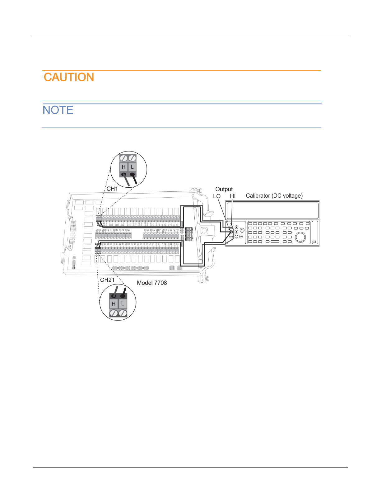
1. Connect the CH1 H and L INPUT terminals to the DC voltage calibrator as shown in the next figure.
2. Install the module in Slot 1 of the DAQ6510.
3. Turn on the power.
4. Allow the instrument to warm up for one hour.
5. Make sure that the front-panel TERMINALS switch is set to REAR.
6. On the front panel of the instrument, select FUNCTION and then select DCV Ratio.
7. On the Home screen, swipe to the CHANNEL swipe screen.
8. Close channel 101.
9. Set the range to 1 V.
10. Set the calibrator output to 1.00000 VDC.
11. Allow the reading to settle.
12. Verify that the ratio reading is between 0.9999926 and 1.000074.
13. Return to the CHANNEL swipe screen and open Channel 1.
Model 7708 Multiplexer Module Instructions for use with DAQ6510
26 077144500 / April 2018
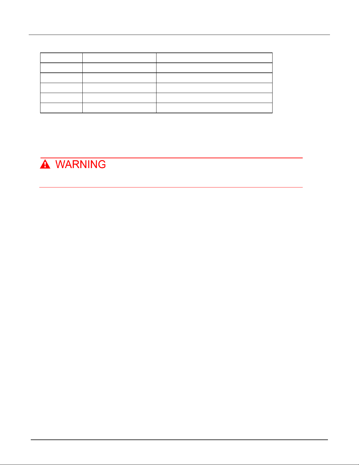
Range
Applied DC voltage
Reading limits (1 year, 18 °C to 28 °C)
100 mV
100.0000 mV
99.9935 to 100.0065 mV
1 V
1.000000 V
0.999969 to 1.000031 V
10 V
10.00000 V
9.99970 to 10.00030 V
100 V
100.0000 V
99.9955 to 100.0045 V
1000 V
300.000 V
299.983 V to 300.017 V
Calibration
The following procedure calibrates the temperature sensors on the modules.
Do not attempt to perform this procedure unless qualified to do so. Failure to recognize and
observe normal safety precautions could result in personal injury or death.
Recommended test equipment
To calibrate the module, you need the following equipment.
▪ Digital thermometer: 18 °C to 28 °C ±0.1 °C
▪ Keithley 7797 Calibration/Extender Board
Extender board connections
The extender board is installed in the DAQ6510. The module is connected to the extender board externally to
prevent heating of the module during calibration.
To make extender board connections:
1. Remove power from the DAQ6510.
2. Install the extender board into Slot 1 of the instrument.
3. Plug the module into the P1000 connector on the rear of the 7797 Calibration/Extender Board.