0771445_7708_Mar2018_077144500.pdf - 第24页
Model 7708 M ultiplexer M odule I nstructions for use with DAQ6510 24 077144500 / April 2018 Verifying frequency To verify the module freq uency: 1. Connect the function generator to the CH1 H and L INPUT term inals of t…

Model 7708 Multiplexer Module Instructions for use with DAQ6510
077144500 / April 2018 23
RTD temperature
To verify the RTD temperature:
1. Connect the precision decade resistance box to the CH1 and CH11 H and L terminals of the module using
four-wire connections. Refer to the first figure in Verifying resistance for connections.
2. Install the module in Slot 1 of the DAQ6510.
3. Turn on the power.
4. Allow the instrument to warm up for one hour.
5. Make sure that the front-panel TERMINALS switch is set to REAR.
6. On the front panel of the instrument, select the FUNCTION key and then select Temperature.
7. On the Home screen, swipe to the CHANNEL swipe screen.
8. Close channel 101.
9. Set the channel to Temperature.
10. Configure the channel for °C units and RTD temperature sensor as follows:
a. Press the MENU key.
b. Select Channel Settings.
c. Set Transducer to 4-Wire RTD.
d. Set 4-Wire RTD to PT385.
11. Source each of the voltages in the table below to verify that the temperature readings are within limits.
Make sure to select the appropriate thermocouple type for each group of readings.
12. Set the decade resistance box to each of the values shown in the table below. Verify that the temperature
readings are within the required limits.
13. Return to the CHANNEL swipe screen, and open Channel 1.
Applied resistance*
Reading limits (1 year, 18 °C to 28 °C)
22.80 Ω
-190.06 °C to -189.94 °C
100.00 Ω
-0.06 °C to +0.06 °C
313.59 Ω
599.94 °C to 600.06 °C
*Based on = 0.00385
Model 7708 Multiplexer Module Instructions for use with DAQ6510
24 077144500 / April 2018
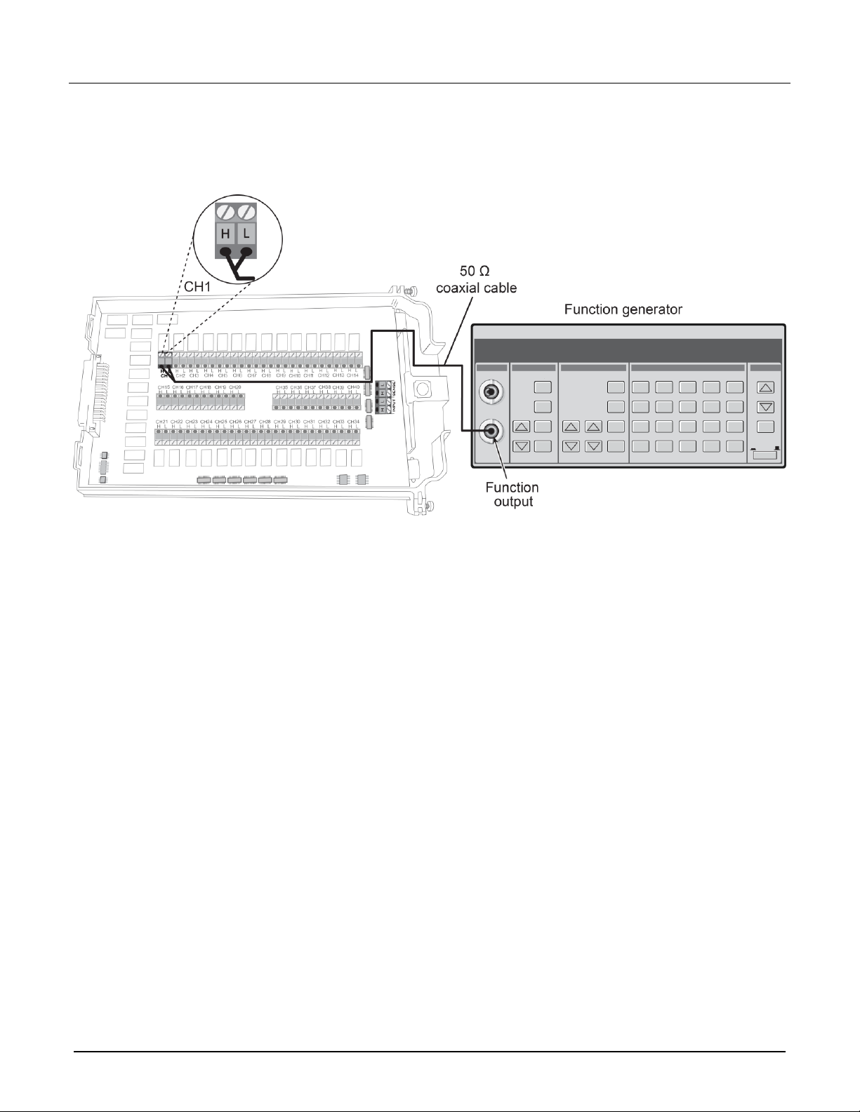
Verifying frequency
To verify the module frequency:
1. Connect the function generator to the CH1 H and L INPUT terminals of the module. Refer to the next figure
for more information.
2. Install the module in Slot 1 of the DAQ6510.
3. Turn on the power.
4. Allow the instrument to warm up for one hour.
5. Make sure that the front-panel TERMINALS switch is set to REAR.
6. Set the function generator to output a 1 kHz 1 V
RMS
sine wave.
7. On the front panel of the instrument, select the FUNCTION key and then select Frequency.
8. On the Home screen, swipe to the CHANNEL swipe screen.
9. Close channel 101.
10. Verify that the DAQ6510 frequency reading is between 0.9999 kHz and 1.0001 kHz.
Model 7708 Multiplexer Module Instructions for use with DAQ6510
077144500 / April 2018 25
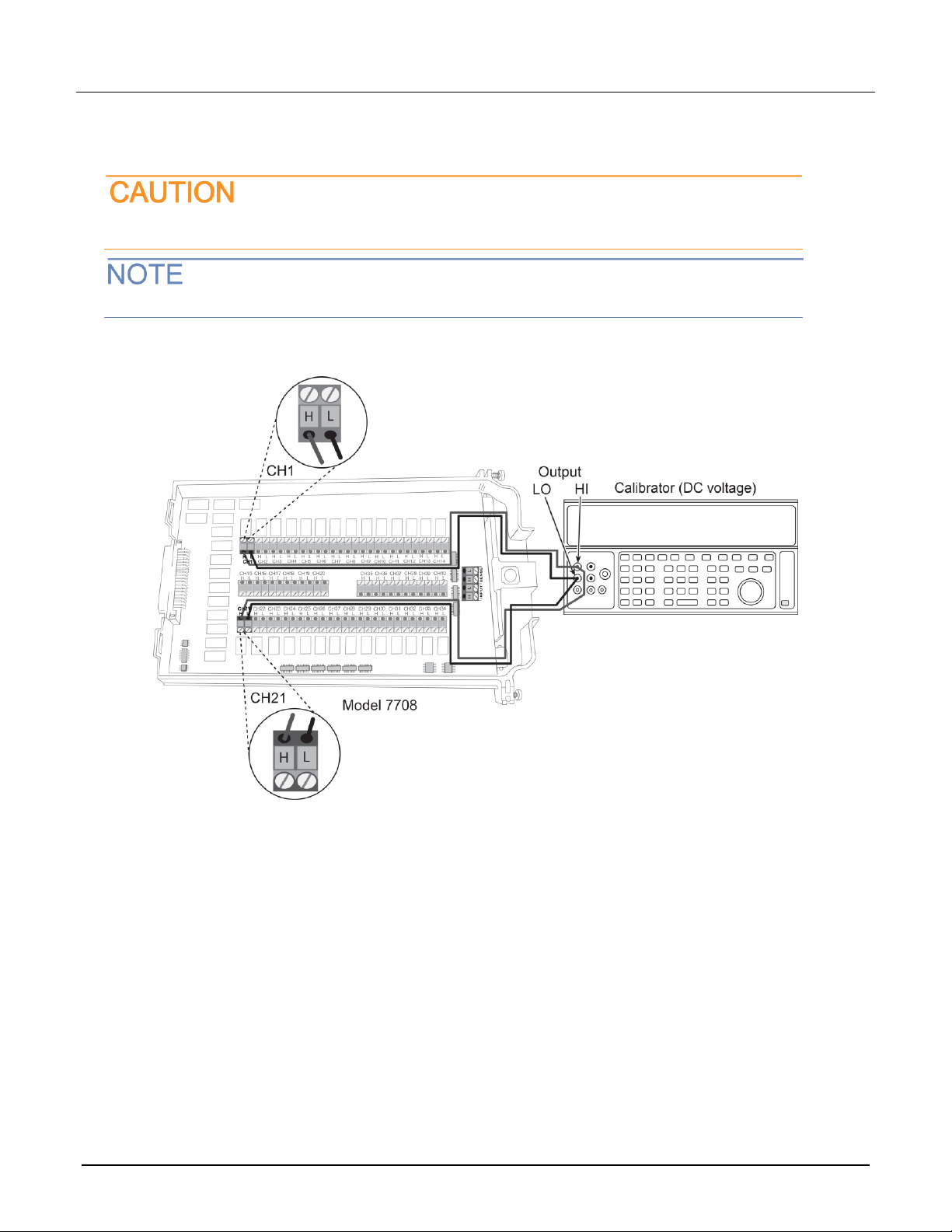
Verifying ratio and average
Follow the procedure below to verify ratio and average.
Do not exceed 300 VDC between plug-in module INPUT H and L terminals or between any
adjacent channels. Failure to observe this precaution can cause instrument damage.
Use shielded cables to minimize noise.
To verify ratio and average:
1. Connect the CH1 H and L INPUT terminals to the DC voltage calibrator as shown in the next figure.
2. Install the module in Slot 1 of the DAQ6510.
3. Turn on the power.
4. Allow the instrument to warm up for one hour.
5. Make sure that the front-panel TERMINALS switch is set to REAR.
6. On the front panel of the instrument, select FUNCTION and then select DCV Ratio.
7. On the Home screen, swipe to the CHANNEL swipe screen.
8. Close channel 101.
9. Set the range to 1 V.
10. Set the calibrator output to 1.00000 VDC.
11. Allow the reading to settle.
12. Verify that the ratio reading is between 0.9999926 and 1.000074.
13. Return to the CHANNEL swipe screen and open Channel 1.