0771445_7708_Mar2018_077144500.pdf - 第4页
Model 7708 M ultiplexer M odule I nstructions for use with DAQ6510 4 077144500 / April 2018 4. Route wire along the c able path and secure with ca ble ties as sho wn. The followin g figure shows connections to channe ls …
Model 7708 Multiplexer Module Instructions for use with DAQ6510
077144500 / April 2018 3
Wiring procedure
Use the following procedure to make connections to the 7708 module. Make all connections using the correct
wire size (up to 20 AWG).
All wiring must be rated for the maximum voltage in the system. For example, if 1000 V is
applied to the front terminals of the instrument, the switching module wiring must be rated
for 1000 V. Failure to recognize and observe normal safety precautions could result in
personal injury or death.
Equipment needed:
▪ Flat-blade screwdriver
▪ Cable ties
To wire the 7708 module:
1. Make sure all power is discharged from the 7708 module.
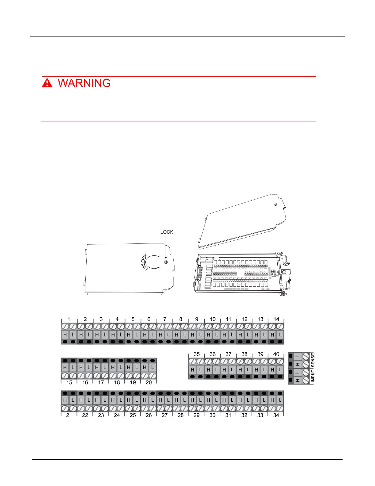
2. Using a screwdriver, turn the access screw to unlock and open the cover.
Figure 2: Screw terminal access
3. Using a small flat-blade screwdriver, loosen terminal screws and install wires as needed. Channel
designations for the screw terminals are shown in the following figure.
Model 7708 Multiplexer Module Instructions for use with DAQ6510
4 077144500 / April 2018
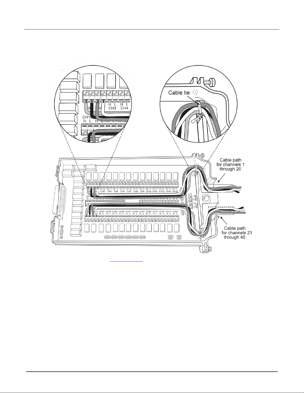
4. Route wire along the cable path and secure with cable ties as shown. The following figure shows
connections to channels 1 and 2.
Figure 3: Wire dressing
5. Record the connections in the Connection log (on page 8).
6. Close the cover.
7. Using a screwdriver, press in the access screw and turn to lock the cover.
Model 7708 Multiplexer Module Instructions for use with DAQ6510
077144500 / April 2018 5
Schematic diagram
The simplified schematic diagram of the 7708 is shown in the following figure. The channels are grouped into
two banks of 20 channels (40 channels total). Backplane isolation is provided for each bank. Each bank also
includes separate cold junction reference points.
The first bank contains channels 1 to 20 and the second bank contains channels 21 to 40. Each channel is
wired with separate inputs for HI/LO, providing fully isolated inputs.
Although the 7708 relays are the latching type (relays hold their state even after power has been removed), all
relay states are set to open a few seconds after either a power cycle or a reset command is issued.
Connections to DMM functions are provided through the module backplane connector of the instrument.
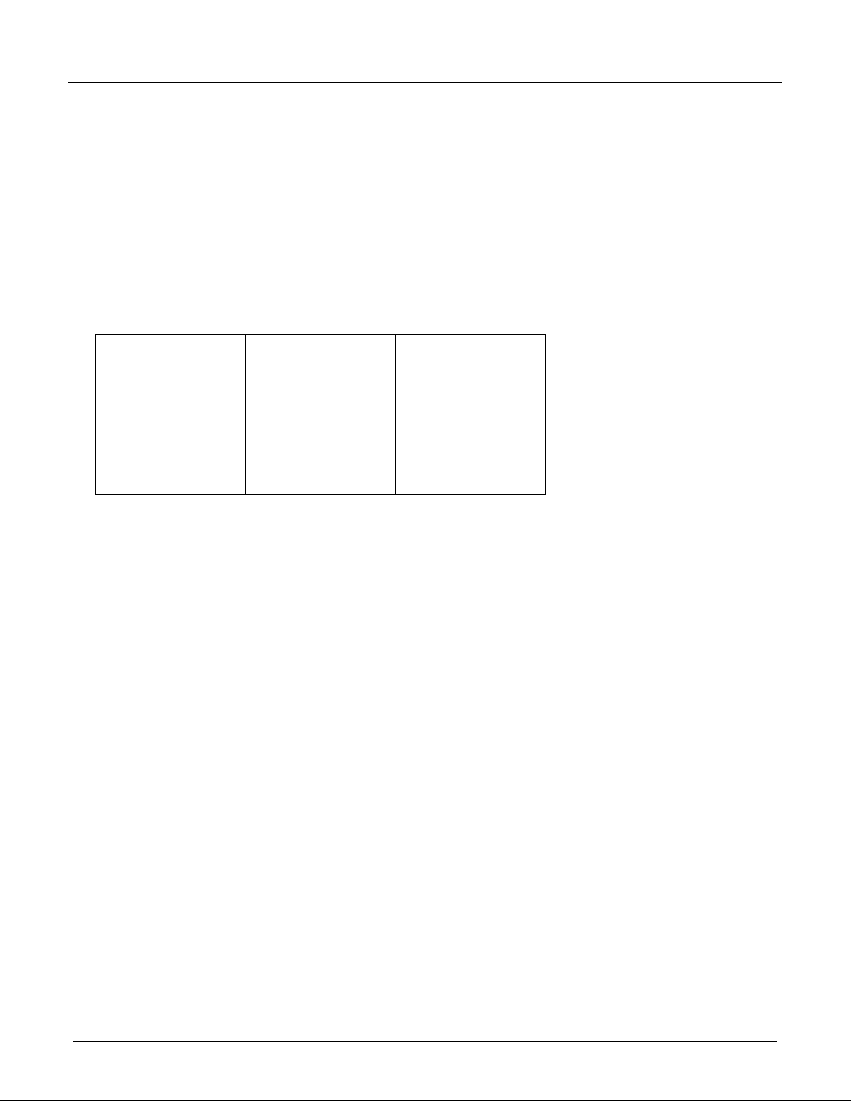
When automatically configured for 4-wire measurements (including 4-wire resistance and RTD temperature),
the channels are paired as shown in the following table. Connect 4-wire sense leads using channels 21 to 40.
CH1 and CH21
CH8 and CH28
CH15 and CH35
CH2 and CH22
CH9 and CH29
CH16 and CH36
CH3 and CH23
CH10 and CH30
CH17 and CH37
CH4 and CH24
CH11 and CH31
CH18 and CH38
CH5 and CH25
CH12 and CH32
CH19 and CH39
CH6 and CH26
CH13 and CH33
CH20 and CH40
CH7 and CH27
CH14 and CH34
The 7708 switching module has 40 channels that can calculate ratio and channel average. The ratio calculation
can be done for the DCV function, and the channel average calculation can be done for the DCV and TEMP
(thermocouples only) functions. Paired channels are used for ratio and channel average. Channels are paired
in the same manner as they are for 4-wire measurements.