QP341 351E规格书.pdf - 第10页
4.2 Machine Configuration Examples Examples of feeder, camera, and nozzle station combinations are shown below. *1. Upper: QP-341E, Lower: QP-351E, MF: IP-series, QP-242E feeders; PF: QP-132E, NP- series Power Feeders *2…
4. Machine Configuration
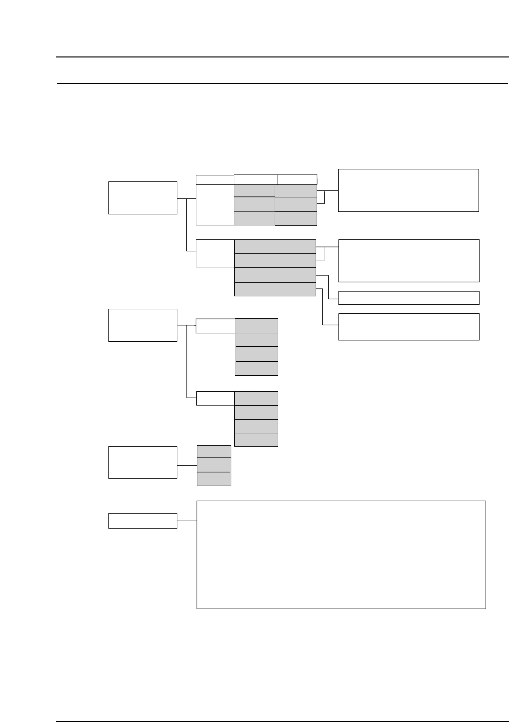
4.1 Machine Configuration Selection
Selection must be made of the type of feeder unit, parts recognition camera, and nozzle
station. Select one of the gray boxes within each group in the figure below.
QP3S006
Feeder Table
5.1
Front
MF
PF
None
A
B
Special
Rear
MFU-6E
PFU-3E
MTU-8E
MTU-9E
6.1.1
6.1.2
6.1.3
6.1.3
6.1.6
6.1.7
6.1.8
STU
Reject parts conveyor
Automatic tape cutter
6.1.10 Area sensor
6.1.9
6.1.10
Tray removal confirmation
Area sensor
Cameras
5.2
Nozzle station
5.3
Front
Rear
Nozzles
Special nozzles
and mechanical chucks
Side covers
Acryl covers (fence, door)
Lead coplanarity check
Placing pressure control
Parts confirmation sensor
Insertion control placing
Vacuum back-up pins
Rear operation panel
Mechanical feeders
Stick feeders
Feeder stand
Feeder set-up jig
Tape splicer
Roller conveyor
Handy Terminal
Kitting Station
HELPS
6.1.4
6.1.5
6.1.11
6.1.12
6.1.13
6.1.14
6.1.15
6.1.16
6.1.17
6.1.18
6.1.19
6.1.20
6.1.21
6.1.22
6.1.23
6.1.24
6.1.25
6.1.26
6.1.27
Other
Line-scan
CCD
LS + CCD
None
Line scan
CCD
LS + CCD
MF: IP-series, QP-242E feeders
PF: QP-132E, NP-series Power Feeders
Nozzle station type B is used if the two-camera system
is used at the rear of the machine.
Note: Refer to the associated section numbers for further details of each item.
Certain items in the list above may be under development or pending.
MFU-6E
PFU-3E
None
QP-341E
QP-351E
None
6.1.6
6.1.7
6.1.8
STU
Reject parts conveyor
Automatic tape cutter
– 6 – QP-341E-MM/QP-351-MM Specifications
Preliminary (January 10, 2000)
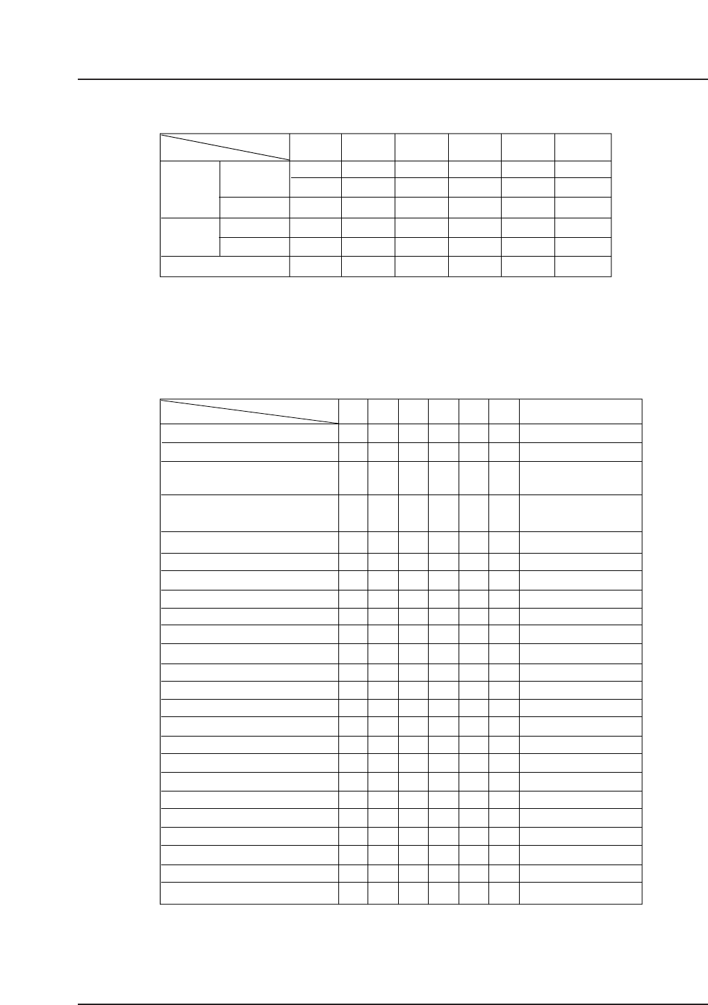
4.2 Machine Configuration Examples
Examples of feeder, camera, and nozzle station combinations are shown below.
*1. Upper: QP-341E, Lower: QP-351E, MF: IP-series, QP-242E feeders; PF: QP-132E, NP-
series Power Feeders
*2. Refer to section 5.3 for details of nozzle station types.
The available options for each of the categories above (A - F) are detailed below.
Example
Options
A
✓
✓
N/A
✓
✓
✓
✓
✓✓
✓
✓
✓
✓
✓
QP3S008
B
✓
✓
C
✓
✓
D
✓
✓
FE
✓
✓
Remarks
✓
✓
✓
✓
✓
✓
–
✓
✓
N/A
N/A
✓
✓
–
–
N/A
✓
N/A
✓
✓
✓
N/A
✓
✓
✓
✓
–
✓
✓
N/A
N/A
✓
✓
–
–
N/A
✓
N/A
✓
✓
✓
N/A
✓
✓
✓
✓
–
✓
✓
✓
✓
✓
✓
–
–
N/A
✓
N/A
✓
✓
✓
N/A
✓
✓
✓
✓
–
N/A
✓
N/A
N/A
✓
✓
–
–
–
N/A
✓
✓
✓
✓
✓
✓
✓
✓
✓
–
N/A
✓
N/A
N/A
✓
✓
–
–
–
N/A
✓
✓
✓
✓
✓
✓
✓
✓
✓
–
N/A
✓
✓
✓
✓
✓
–
–
–
N/A
✓
✓
✓
✓
✓
STU
Reject parts conveyor
Automatic tape cutter
Automatic tape cutter
Lead coplanarity check
Placing pressure control
Vacuum back-up pins
Parts confirmation sensor
Insertion control placing
Acryl covers (fence, safety doors)
Rear operation panel
Tray removal confirmation
Area sensor
Sliding side door cover
Roller conveyor
HELPS
Handy Terminal
Kitting Station
Mechanical feeders (BFC, IPC, MF)
Power Feeders
Stick feeder
Feeder stand
Feeder set-up jig
Tape splicer
✓: Available options (factory or onsite installation) N/A: Not applicable –: Pending
(for MFU, PFU)
(QP-341E-MM only)
October 1999
Under development
Under development
Under development
Under development
Specify with order
Specify with order
Specify with order
(#1) An MFU compatible with stick feeders can be used at the front of the machine if specially requested.
(#1)
(351E) (351E)
Example
Items
Rear
A
MFU-6E
N/A
LS
B
MFU-6E
MFU-6E
LS
LS
C
MFU-6E
MTU-9E
LS
LS
D
PFU-3E
PFU-3E
LS
LS
FE
PFU-3E
PFU-3E
LS
LS/CCD
LS
LS
BBBBBB
Feeder
Unit
Front
Rear
Camera
Nozzle station type
(*2)
Front (*1)
N/A
MF
MF
PF PF
PF
MFU-6E
PFU-3E
MTU-9E
– 7 – QP-341E-MM/QP-351-MM Specifications
Preliminary (January 10, 2000)
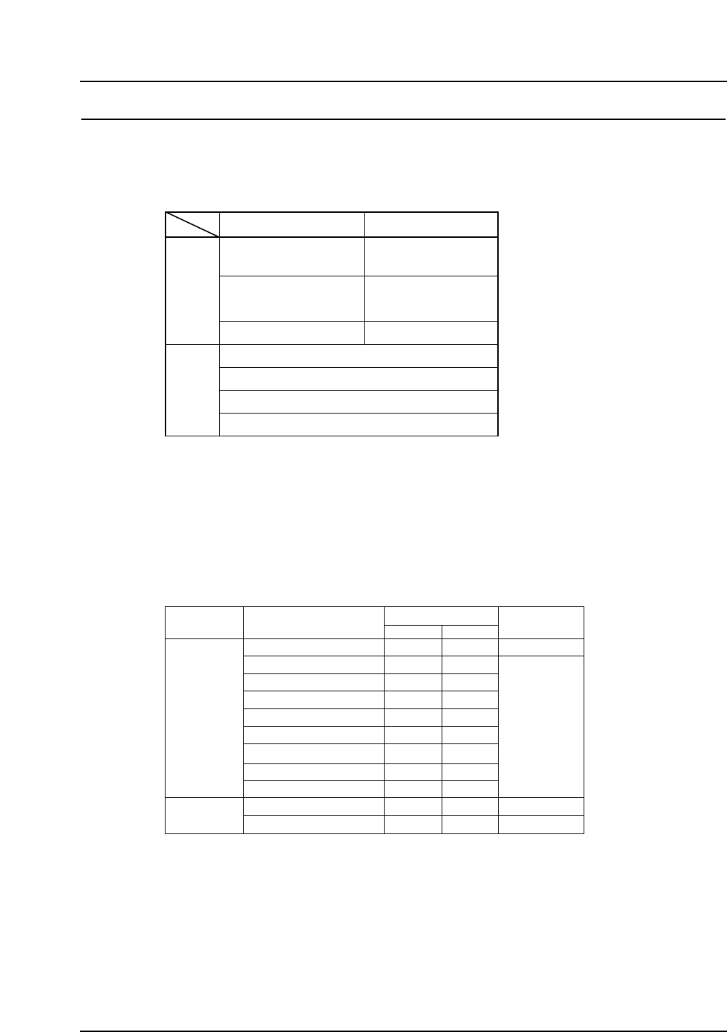
5. Feeder, Camera, and Nozzle Station Selection
5.1 Feeder Table
Parts supply units can be selected as detailed below.
Notes: The front supply unit on the QP-341E is fixed.
MF: IP-series and QP-242E mechanical feeders
PF: QP-132E and NP-series Power Feeders
A safety fence is attached during use of the MFU-6E, and IP-series/QP-242E
mechanical feeders.
Refer to the table below for the maximum number of feeders that can be set.
Notes: The fixed supply side feeder capacity is the same as for an MFU-6E or a PFU-3E.
Stick feeders for the MFU-6E can only be used on the rear side of the machine, unless
use at the front of the machine is specially requested.
The tape index lever on IPC-type feeders must be changed prior to use.
72 mm and wider Power Feeders, and stick feeders are under development for the
PFU-3E.
Tape feeders
Stick feeders
Max. feeders
8 mm (1P)
12 mm (1P)
16 mm (2P)
24 mm (2P)
32 mm (2P)
44 mm (3P)
56 mm (4P)
72 mm (5P)
88 mm (6P)
7 mm ≤ W ≤ 28 mm (2P)
25 mm ≤ W ≤ 48 mm (3P)
24
24
11
11
11
8
6
5
4
11
8
Type - 1
Type - 2
Remarks
Packaging sizeFeeder type
24 x 2
24
12
12
12
8
6
–
–
–
–
MFU-6E PFU-3E
(#1): 8 mm double channel feeder on the PFU.
#1
QP3S010
Front
Rear
QP-341E QP-351E
Fixed mechanical
feeder table (MF)
Fixed Power Feeder
table (PF)
MFU-6E
PFU-3E
MFU-6E
PFU-3E
MTU-8E
MTU-9E
No installation No installation
QPS3S042
– 8 – QP-341E-MM/QP-351-MM Specifications
Preliminary (January 10, 2000)