QP341 351E规格书.pdf - 第18页
6.1.6 Single Tray Unit (STU-1/2) (Optional) (Under Development) A Single Tray Unit is mounted on an MFU-6E or PFU-3E to supply tray parts. The STU requires a separate air and power supply. # 1 : Attached at the front sid…
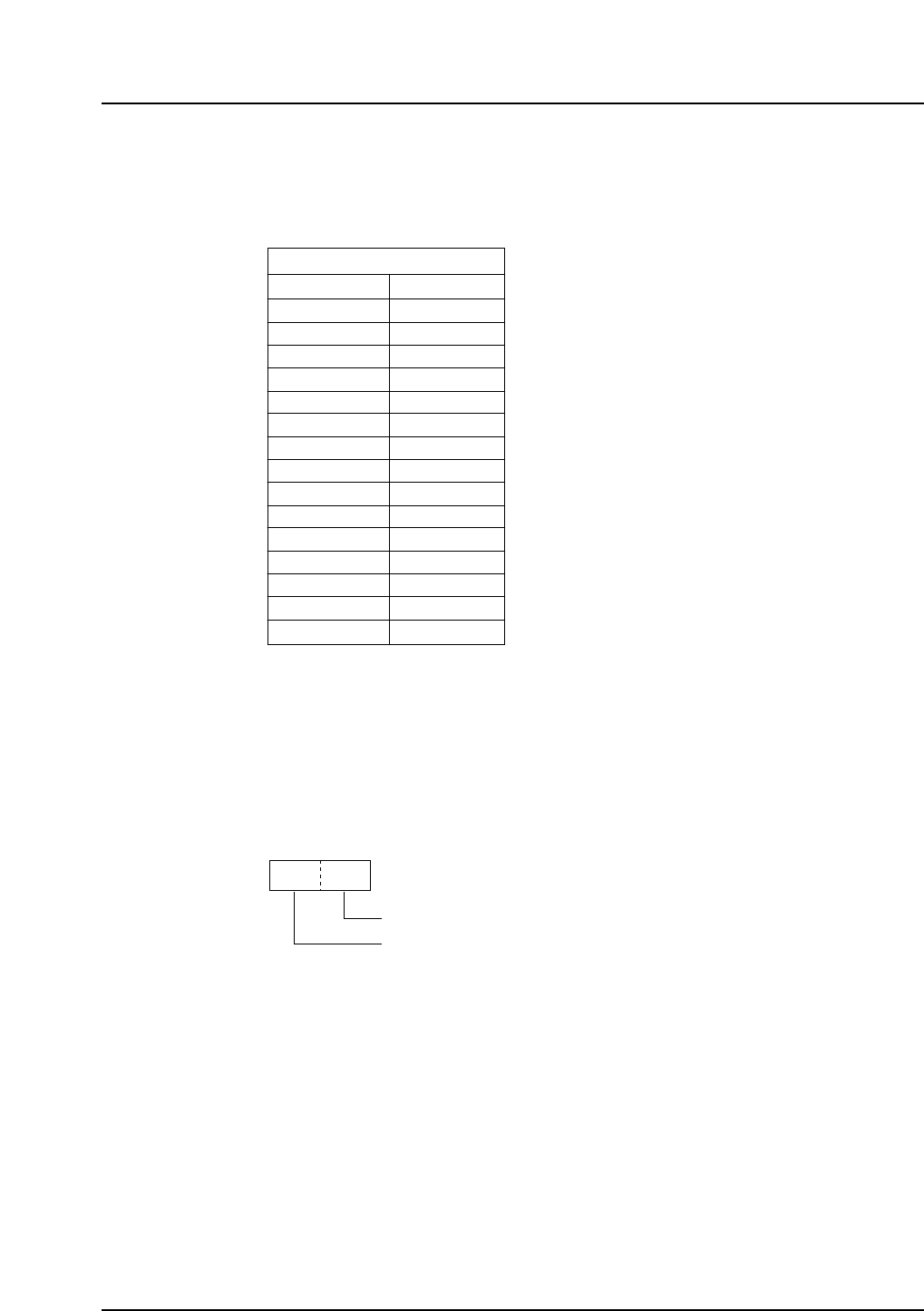
6.1.4 Nozzles (Optional)
Three single nozzles are selected as required from the nozzles held in the nozzle
station.
Nozzle types (Scheduled)
Notes: Contact Fuji for details of support for nozzle types other than those listed in the
table above.
Fuji carries out in-house testing for the handling of connectors. Parts for
testing are required for appraisal by Fuji.
The nozzle information in the table above is derived at in the following manner.
6.1.5 Special Nozzles and Mechanical Chucks (Optional)
• Used to handle parts such as connectors that cannot be handled with
regular nozzles. For details, contact your Fuji representative with the
following information.
• Sample and detailed illustrations of the parts to be handled.
• Packaging information (reel, stick, tray etc.)
• Mounting history
Length of the nozzle tip (1/10 mm)
Nozzle outer diameter (1/10 mm), G: vacuum pads
025G 270
QP3S021
Single nozzle
100
100
270
270
270
270
270
270
270
270
270
270
270
270
270
007
010
013
018
025
025G
037
050G
070
080G
100
150
150G
175G
200
Nozzle diameter Nozzle length
QP3S020
– 14 – QP-341E-MM/QP-351-MM Specifications
Preliminary (January 10, 2000)
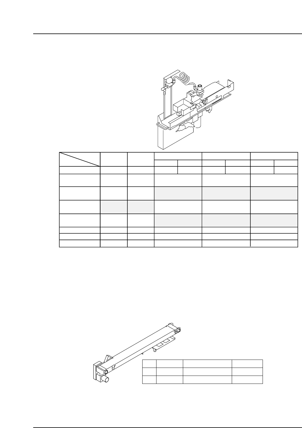
6.1.6 Single Tray Unit (STU-1/2) (Optional) (Under Development)
A Single Tray Unit is mounted on an MFU-6E or PFU-3E to supply tray parts.
The STU requires a separate air and power supply.
#1: Attached at the front side on the QP-341E.
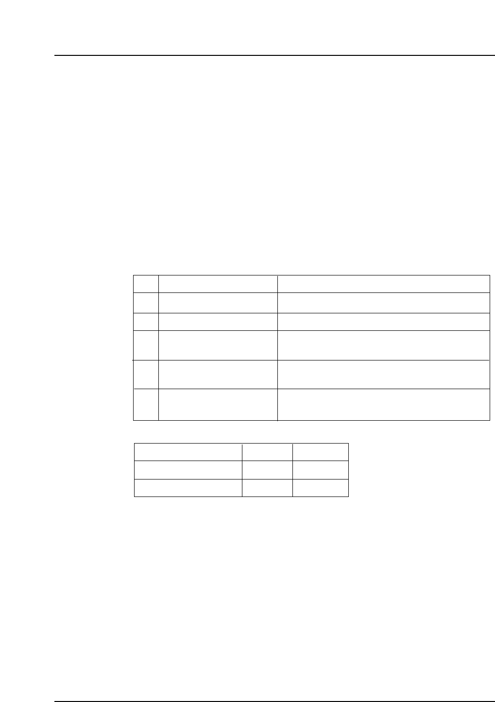
6.1.7 Reject Parts Conveyor (Optional)
A reject parts conveyor is installed on MFU-6E or PFU-3E. (It can also be
installed at QP-341E fixed side.) Two models of conveyor are available: MFU-6E
type and PFU-3E type. Select an M or L size unit depending on the parts being
handled.
QP3S024
Size
M
L
Belt width
33.4 mm
78.0 mm
Part size
27 x 27 – 31 x 31 mm
74 x 74 mm
Feeder slots
3
7 (6)*
* The value in parentheses indicates the number of slots taken up if a reject parts
conveyor is used with an STU.
QP3S022
Supply unit
Tray size (mm)
Tray stack
height (mm)
Stack number
Empty tray
weight (g)
Slots occupied
Max. no. of units
Machine side
STU-1
MFU-6E
100 x 150 to
150 x 330
4 to 50
Up to 240
9
2
Rear
STU-2
MFU-6E
50 x 50 to
102 x 102
4 to 50
Up to 240
7
3
Rear
STU-4
MFU-6E
STU-7
MFU-3E
2-inch tray
50.8 x 50.8
50
4
6
Front/rear
STU-5
MFU-6E
STU-8
PFU-3E
4-inch tray
101.6 x 101.6
25
7
3
Rear
STU-6
MFU-6E
STU-9
PFU-3E
JEDEC tray
135.9 x 322.6
40 (thin)
25 (thick)
9
2
Rear
#1
#1
– 15 – QP-341E-MM/QP-351-MM Specifications
Preliminary (January 10, 2000)
6.1.8 Automatic Tape Cutter (Optional)
The automatic tape cutter is attached to an MFU-6E/PFU-3E or the fixed supply
side of the machine, and is used to cut off the waste tape when it reaches a given
length. If the tape cutter is attached to the fixed supply side, it must be installed
when the machine is built.
6.1.9 Tray Removal Confirmation (MTU-9E) (Optional)
A sensor is used to detect the presence of empty trays. This function is used to
prevent a wrongly removed tray from causing damage to the machine.
6.1.10 Area Sensor (Optional)
An area sensor is used to increase the safety of the MTU-8E/9E during automatic
operation.
6.1.11 Side Covers (Optional)
The covers available are detailed in the table below.
6.1.12 Smoke Colored Acryl Covers (Optional)
The brown acryl covers on the doors and fences can be replaced by smoke
colored covers.
B
C
D
E
F
Fixed type
Sliding-door type
Sliding-door type
(with safety switch)
Sliding-door type (partitioning)
Cannot be removed in multiunit setup.
Can be opened for easy maintenance in multiunit setup.
Can be opened without removal of screws to enable
easy maintenance on machines equipped with MTUs.
Same as C, but transparent. Attached to left side in
multiunit setup.
No cover fitted Can only be specified for the right side in multiunit setup.
Cover type DescriptionCode
Stand-alone or multiunit
Multiunit C, E
B, C, D
B, C, D
Left side Right sideSetup
F
Side cover configurations are shown in the table below.
QP3S044
– 16 – QP-341E-MM/QP-351-MM Specifications
Preliminary (January 10, 2000)