QP341 351E规格书.pdf - 第25页
6.1.22 Feeder Set-up Jig (Optional) Used to hold feeders in a vertical position while maintenance is being performed, or during the setting of a new reel of parts. 6.1.23 Tape Splicer for Power Feeders (Optional) This op…

6.1.21 Feeder Stand (Optional)
The feeder stand has been designed so that feeders can be safely stored in a state
ready to use. The feeder stand is comprised of three shelves in the following
combinations:
• IP / QP-242E type feeders
• Power Feeders (QP-132E/NP-series Power Feeders)
Notes: 72 and 88 mm Power Feeders are under development.
When using a combination of 8 mm, 12 mm feeders and 16 mm, 24 mm feeders,
the stand capacity can be calculated using the formula 22a + 33b ≤ 1100 (where
"a" is the number of 8 mm, 12 mm feeders, and "b" is the number of 16 mm, 24
mm feeders).
The figures quoted for the capacity of the Power Feeder stand assume the upper
shelf is holding Power Feeders and the lower shelf is holding reel holders. The
holding capacity of the stand is doubled if the upper and lower shelves are used
for Power Feeders only.
Feeder stand combinations
8 or 12 mm feeders
16 or 24 mm feeders
32 mm feeders
44 mm feeders
56 mm feeders
72 mm feeders
88 mm feeders
Capacity
50
33
QP3S035
Feeder stand combinations
8 or 12 mm feeders
16 or 24 mm feeders
32 mm or stick feeders
44 mm or stick feeders
32 or 44 mm feeders
44 mm or Type 1 and
Capacity of each shelf
31
22
19
15
8 + 8
9 + 5
Total: 14
56 mm or Type 2
QP3S034
– 21 – QP-341E-MM/QP-351-MM Specifications
Preliminary (January 10, 2000)
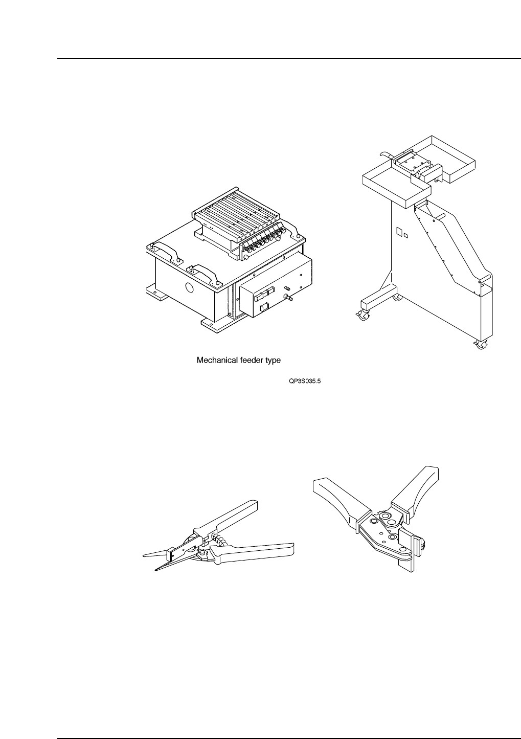
6.1.22 Feeder Set-up Jig (Optional)
Used to hold feeders in a vertical position while maintenance is being performed,
or during the setting of a new reel of parts.
6.1.23 Tape Splicer for Power Feeders (Optional)
This option facilitates the splicing of new tape to the end of almost spent tape on
the PFU.
QP3S037
Hand cutter Splicer
Power Feeder type
QP3S036
– 22 – QP-341E-MM/QP-351-MM Specifications
Preliminary (January 10, 2000)

6.1.24 Roller Conveyor (Optional)
The roller conveyor employs rollers under the conveyor belt to improve PCB
conveyance.
The roller conveyor is required when the PCB weight (including supporting
pallet) exceeds 1 kg. PCBs of up to 2 kg in weight can be conveyed using rollers.
6.1.25 Handy Terminal (Pending) (Optional)
• Allows the operator to view and enter device-related data that is normally
displayed at the machine monitor.
• Equipped with a pen type entry device for use during bar code reading and
changeover. Feeder setting errors can be prevented by using the Handy
Terminal.
• Power Feeder loading positions can be checked by reading the feeder ID.
6.1.26 Kitting Station (Pending) (Optional)
The network established between the Kitting Station and the feeders/PFUs gives
the operator access to reports relating to part and reel types, feeder and splicing
data, and device slot data in the program. The Kitting Station is a CIM tool
designed to maximize production efficiency.
Note: The computer on which the Kitting Station software is installed must be
prepared in advance by the user.
6.1.27 HELPS (Pending) (Optional)
HELPS is Fuji's automatic production program changeover system, and stands
for High Efficiency Line Production System. The main functions of the HELPS
system are: • Automatic program changeover
• Conveyor width changeover
• Display of changeover instructions for the operator.
6.1.28 Other
Feel free to talk to us or to your Fuji representative regarding customization of
your order or clarification of any points in this document.
– 23 – QP-341E-MM/QP-351-MM Specifications
Preliminary (January 10, 2000)